*** This version of Confluence is for testing only and contains a copy of content from June 29th 2026. No changes will be preserved. ***

 user-c73ee, last updated on Sep 29, 2008
2 minute read
user-c73ee, last updated on Sep 29, 2008
2 minute read
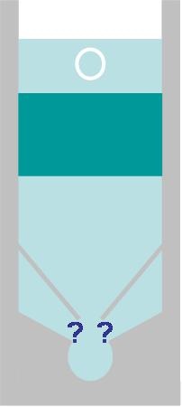
To model the flow (experimentally/computationally) distribution in the bottom of a sedimentation tank, and to devise an optimal design for creating uniform flow.
CFD Sedimentation Tank Simulation goals and meeting minutes.
Unable to render embedded object: File (existing design.jpg) not found.
In the latest design of sedimentation tank, we use a V-shaped tank bottom to collect and drain the settled flocs, with influent pipes installed along the slopes.
Unable to render embedded object: File (modified design.jpg) not found.
In a newly proposed design, we will make better use of the space under the surface of V-shaped bottom, replacing the concrete with void space for influent water, and create water inlet at the bottom of the slopes. In this new design, we use less concrete and less pipes to bring down the cost, and avoid the unstability of upward flow caused by multiple pipes at the bottom.
The major challenge in this new design is how to configure geometry of the water inlet at the bottom of the slopes to create flows as uniform as possible.
Intuitively, there are three basic situations of the water inlets.
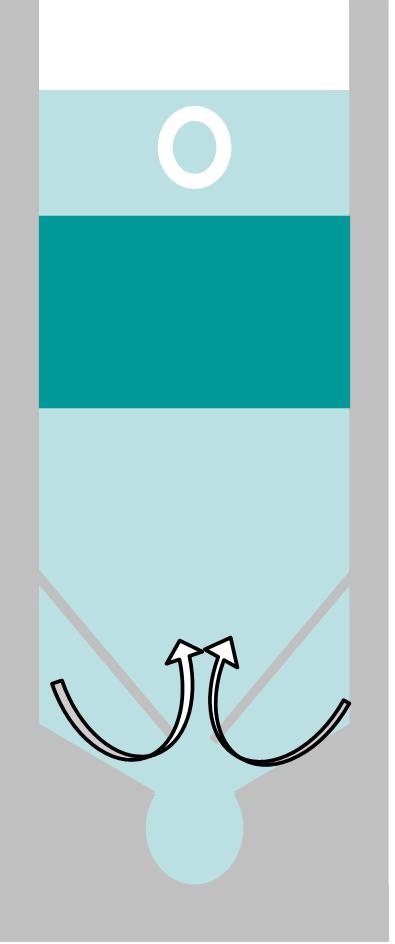
Openings for water inlets on bothsides. Water flows from both sides, collide with each other and rise in the middle.
Unable to render embedded object: File (single flow region.jpg) not found.low region.
Opening for water inlets on one side. Water flows from one side, collide and rise along with the slope on the other side.
 low region.
Opening on neither side. No flow from either side.
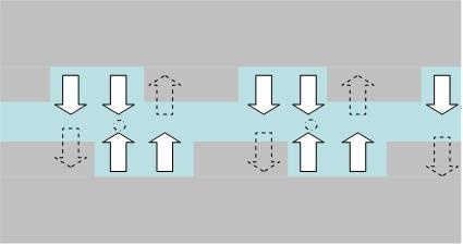 low region.