*** This version of Confluence is for testing only and contains a copy of content from June 29th 2026. No changes will be preserved. ***

 user-7ca00, last updated on Aug 11, 2008
9 minute read
user-7ca00, last updated on Aug 11, 2008
9 minute read
The flocculator design algorithm is actually a series of functions working together. The main function - flocculator - is sent the required inputes and called by the master program. In turn, it calls the functions - uturnhole, shortcircuit, bafflepositions, and Gθmincheck. Ultimately, the flocculator function outputs the necessary values for the design report and the AutoCAD team. The function relies on these assumptions in order to create its final design.
Flocculation Tank Program Inputs
Flocculation Tank Program Outputs
Flocculation Tank AutoCAD Drawing Program
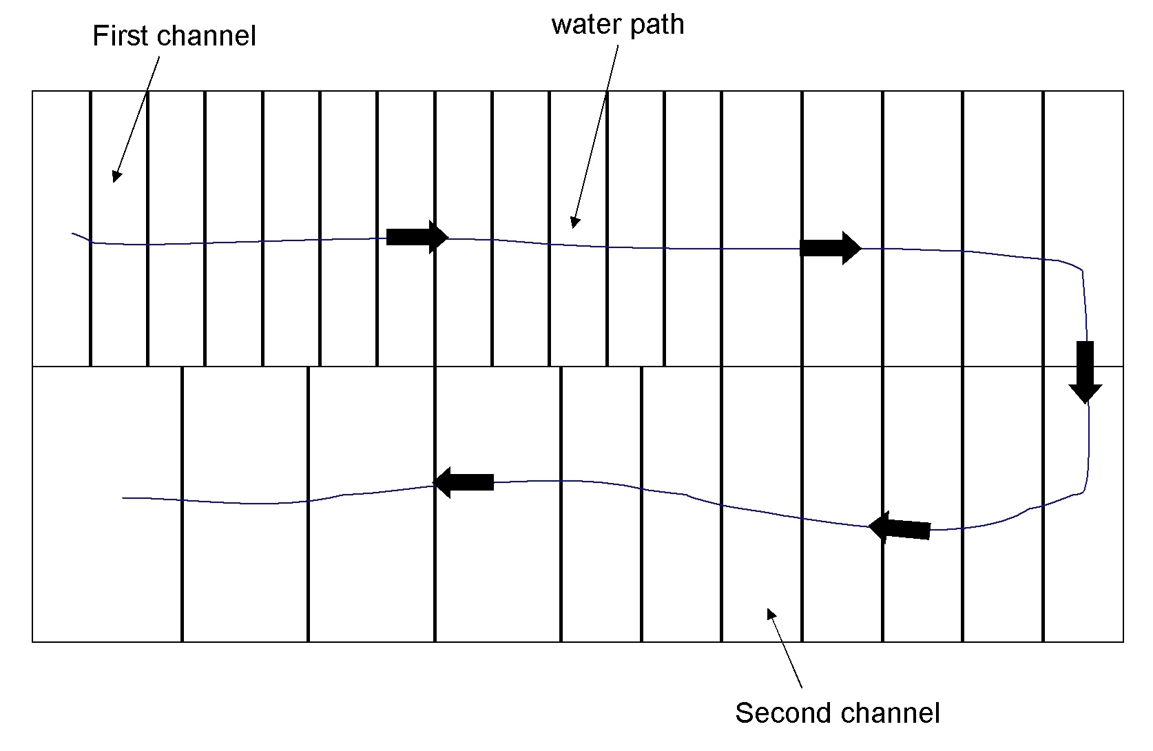
In order to create a square or rectangular footprint, the dimensions of the flocculator must be similar to that of a sedimentation tank. In order to maximize the amount of tank used for flocculation and limit the amount of materials used unnecessarily, the width of the floc tank is half the width of a sedimentation tank. This decreases the flow area thereby allowing for higher Gθ values with bigger baffle spacings. In our current design, the flocculator is comprised of two adjacent channels [#Figure Floc1] where the water makes a 180 degree turn between the channels.
The length of a channel is the same as the length of the sedimentation tank. Finally, the depth of the water at the end of the flocculator must be the same as the depth of water in the sedimentation tank. Due to head loss through the baffles, the water depth will be greater at the beginning of the tank. Additionally, the design calls for 10cm of free space between the water surface and the top of the tank.
After determining the dimensions of the flocculator, the function calculates the baffle spacing and number of baffles in each spacing. The baffle spacing is found using the following [#equation].

In this equation G is a vector of the ideal velocity gradients at each spacing. These values were calculated based on the recommendations of Shulz and Okun. A flocculator requires a minimum amount of mixing to be effective. The degree of mixing is expressed by Gθ, a dimensionless value found by multiplying the velocity gradient by the residence time. This value must be found at low flow in order to ensure that the tank does not fail when the actual flow rate is less than the design flow rate. The design assumptions assumes an ideal Gθ value of 5000 based on the flocculator at Ojojona. This value is divided by the number of baffle spacings in order to determine what Gθ value each section must achieve. The number of baffles in the first two spacings is determined based on the values of G and θ at the design flow rate. This is done to ensure that large G values do not break up flocs. The number of baffles in the final spacing is determined based on Gθ at low flow. This guarantees that the Gθ value for the entire tank is large enough. The number of baffles in the final section should be the greatest. Interestingly, Gθ is not dependent on the baffle spacing used and is instead determined by the ratio of flow rate to tank width. Regardless of the number of baffle spacings used, tanks with equal flowrates should have the same number of baffles. Therefore, the best way to increase Gθ is to decrease the width of the tank.
The flocculator function does a series of simple calculations to determine the head loss through the tank. This is done by finding the [#head loss] through a single baffle in each of the three baffle spacings.

Multiplying this value by the number of baffles in each section and summing the results provides the total headloss for the tank. The water depth at the end of the flocculator plus head loss gives the water height at the beginning of the tank. The depth of the tank should be based on this water height plus freeboard to ensure that it will not overflow.
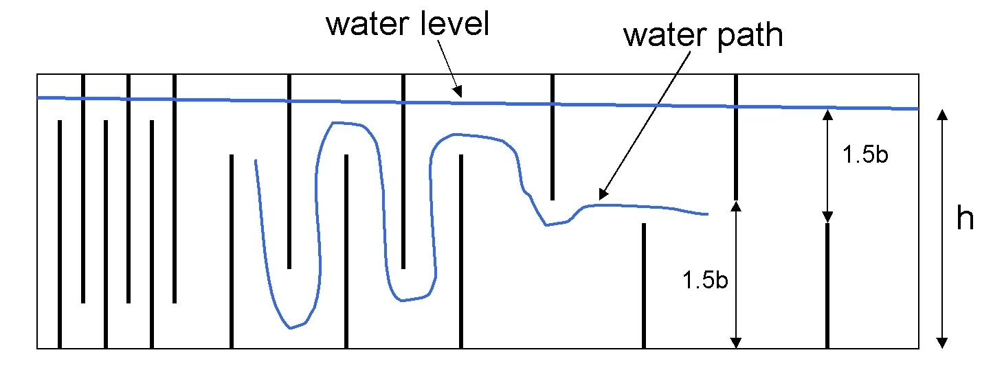
The flocculator function then calls another subfunction - shortcircuit. In a typical flocculator design the free space between the end of a baffle and either the water surface or the bottom of the tank is equal to 1.5*baffle spacing.The length of the upper and lower baffles is different. An upper baffle extends from the top of the tank downward until it is 1.5*b from the bottom of the tank. A lower baffles extends from the bottom of the tank up until it is 1.5*b from the water level at the end of the tank. This function does not account for the change in water level due to headloss throughout the tank. At large baffle spacings, the 1.5*b constraint will likely cause short circuiting. [#Short circuiting] occurs when adjacent baffles no longer overlap and water can flow straight through the tank rather than up and down around the baffles. Quantitatively, this occurs when 3*baffle spacing approaches the water depth.
Our design demands a baffle overlap of at least 2 cm. The shortcircuit function checks to make sure this minimum value is achieved. If not, the function calculates a [#new ratio] between baffle spacing and the height of the horizontal channel above or below a baffle.

The function than recalculates the baffle length of the baffles in this spacing section. The function returns a revised vector of baffle lengths.
The flocculator function is currently only capable of handling designs which call for two channels. The function calls on of two subfunctions in order to determine the baffle coordinates in these two channels. These values are used by the autoCAD team to draw the baffles. The function outputs a separate matrix for each channel. Bafflepositions.1channel is called if the length of the flocculator as determined by number of baffles time baffle spacings is less than the length of a single channel. In reality, this flowrate demands only a single channel, however in our plants the second channel will be filled with baffles at the greatest baffle spacing. Conversely, the functions calls bafflepositions.2channels if the length of the flocculator required by baffle spacing times number of baffles is greater than the length of the first channel.
The function returns a separate matrix for each channel. Each matrix has three columns. The origin (0,0) is set at the beginning and top of the first channel. The first column is the x position of each baffle. The second and third columns are the endpoints of the baffle. One major weakness in the current flocculator design process is that this subfunction will only work for two channels. This should be changed to make the program more versatile. The function first finds the x position of every baffle in the first channel. See the Flocculation Function mathCAD file for the step by step process. It checks to make sure that a baffle is not placed too close (less than the current baffle spacing) to the wall at the end of the channel. If a baffle is too close, this baffle is removed and the function begins assigning the x positions to the baffles in the second channel. The x coordinates in this vector are relative to the same datum; however the positions are found starting where the water enters the channel and working backward. Therefore, the x coordinates get smaller with each entry. Once again, the function checks to make sure that a baffle is not placed too close to the wall. If the length predicted by baffle spacing*number of baffles is less than the length of the two channels, extra baffles are added at the end of the second channel. These baffles will have the largest baffle spacing. Conversely, if the total length of the flocculator is less than the length demanded by baffle spacing*number of baffles, baffles are removed from the largest baffle spacing.
After assigning the x positions, the function adds the y coordinates to the matrices. Once again, the function assigns all the values for the first channel first. A baffle either starts at the top of the tank (y = 0) and extends downward an amount equal to the length or a baffle starts at the bottom of the tank (y = tank height) and extends upward an amount equal to its length. The first baffle in the first channels start at the beginning of the tank and extends upward. The function returns the matrix for each channel as well as the total number of baffles in the tank.
Next, the function calls its first subfunction - uturnhole. For structural reasons, the wall between the two channels must extend from one side of the flocculator all the way to the other. Therefore, the water must flow though a hole in this wall to move from one channel to the next. The shear through this hole must not break up flocs and the width of this hole must not be greater than the baffle spacing at the beginning of the second channel. In order to guarantee that the hole will not break up flocs, the shear through the hole should be equal to the shear through the last baffle spacing. In other words, the area of the hole should equal the flow area (channel width * baffle spacing) at the largest spacing. The function determines the baffle spacing at the beginning of the second channel and sets the width of the hole to this value minus a safety factor (1.5 cm in our current design). The height of the hole must be sufficient to equate the areas. The hole is a square for ease of construction. Additionally, it is assumed that the hole will take up a significant portion of the wall and therefore it can be placed in the center of the wall, rather than up or down depending on baffle placement. Ultimately, the function returns a vector including the width and height of the hole.
Finally, the flocculator function calls a subfunction, Gθmin.check, which calculates the Gθ value now that all the baffles have been placed. This function. This new value is compared to the absolute minimum allowable Gθ value for the tank (4500 in our design). The function returns a 1 if the Gθ is too low and a 0 otherwise. The flocculator function returns an error message if Gθmin.check returns a 1.
During the spring semester 2008, it came to our attention that perhaps our calculation of Gθ was flawed. Instead of calculating a θ value (residence time) for the entire tank, we should only we accounting for the residence time during which flocculation is occurring. We hypothesize that the flocs are mainly colliding over a distance 2*baffle spacing after making a u turn around a baffle. Thereby, the residence time for each baffle should be the tank flow rate (Q) divided by the relevant volume (width of tank * baffle spacing * 2baffle spacing). The residence time for the entire tank would in turn be this value times the number of baffles. Under this new assumption, we needed to find a new minimum value of Gθ for the tank as well as ideal G values for each baffle spacing. Following is an outline for how these calculations were carried out, and [here|^new g and gtheta.xmcd] you will find the associated calculations.
Water treatment specialists, Okun and Shulz make the following recommendations for a vertical flocculator:
Velocity between 0.1 and 0.3 m/s
Water depth of at least 1 m
Baffle spacing of at least 45 cm
A flow rate of 10,000 m3/day or greater
Using these values they calculated ideal G values of 15 s-1, 45 s-1and 75 s-1 and a Gθ minimum of 20,000. However, these calculations neglect the fact that flocculation actually occurs in only a portion of the tank. Using these initial parameters we were able to recalculate the values for G.
First, we used Okun and Shulz's G values to find the baffle spacing in each section using the equation

This equation was derived from

where

and

.
After finding the baffle spacing, we could use this value to determine their actual G values based on our hypothesis. We found the new ideal G values to be 19 1/s, 83 1/s, and 166 1/s.
In order to find the minimum Gθ for an effective tank, we used the parameters from the flocculator in Ojojona since we know that one is creating decent sized flocs. Using the baffle spacing and flow rate we found the G and θ values for the tank.

and

We calculated a minimum value of approximately 4500. This is likely an overestimation since the flocs might be sufficiently large in the tank before the water reaches the end. However, for now, this is a satisfactory value. In the future it would be best to work with the pilot plant team to determine a more precise value.
The automated design master program uses these values to determine the baffle spacing and number of baffles in a flocculator.