*** This version of Confluence is for testing only and contains a copy of content from June 29th 2026. No changes will be preserved. ***

 user-d6d20, last updated on May 07, 2008
4 minute read
user-d6d20, last updated on May 07, 2008
4 minute read
The goal of the flocculator is to create the largest flocs possible without causing shear-induced floc breakup. Its hydraulic residence time is to be on the order of 5 minutes.
A theoretical model was used to model hydraulic flocculation in the flocculator. The model was first developed by Dr. Monroe Weber-Shirk and was subsequently updated as more empirical data became available. The model predicts the amount of mixing, which is the product of shear and residence time, required to achieve a target floc size. The calculation is based on the concentrations of kaolin clay and aluminum sulfate in the feed, and an efficiency factor that accounts for the fact that not every collision between two particles causes them to stick together. In addition, the model calculates the maximum shear that a floc can withstand as a function of how much mixing it has gone through, based on the empirically-determined shear strength of aluminum sulfate flocs.
It has been experimentally observed that the biggest flocs that the existing demo plant can create is about 0.7 mm in diameter. Hence, the target floc size was set to 1 mm. The feed clay concentration was set to 500 mg/L, with a corresponding turbidity of 180 NTU. The aluminum sulfate dose was set to 45 mg/L. Finally, the efficiency factor was experimentally determined to be 0.2.
The flocculator design program was initially written in Fall 2007 as part of a CEE 454 final project, to create a design with varying baffle spacing such that the flocculator is as compact as possible. Since the new demo plant will be constructed out of the corrugated plastic, it will have uniform channels. The program was therefore altered to accept a preset, uniform baffle spacing.
The program starts designing the flocculator from its exit. The dimensions of the last channel is determined from the baffle spacing, channel width and the given height of water. The degree of mixing provided by each channel is calculated from the plant flow and the dimensions of the channel. The number of channels required is then obtained by dividing the required amount of mixing calculated by the flocculation model by the degree of mixing provided by each channel. The maximum shear in each channel is also calculated using the channel dimensions and plant flow. The maximum shear is constant for all the channels since the channel dimensions are uniform.
The head loss in each channel is calculated by summing the frictional loss caused by the channel walls, and the expansion loss caused by the 180° turn at the end of the channel. The head loss is incremented every channel to determine the hydraulic profile. A given headroom is added to the height of the water in the first channel to give the height of the flocculator. The clearance between the end of each baffle and the water surface or flocculator floor is 2.5 times the baffle spacing.
The new flocculator has 31 channels and is about 35 cm long. The corrugated plastic dictates that each channel will be 0.7 cm by 1 cm. The clearance between the end of each baffle and the water surface or flocculator floor is 2.5 cm. The plant flow is 100 mL/min and the height of the water in the last channel is 25 cm, in order for the new flocculator to be compatible with the existing sedimentation tank. The height of the water in the first channel is about 26 cm and the headroom is set to be 2 cm. The flocculator is therefore 28 cm tall. The maximum shear in the flocculator is 45 /s and the total mixing is 5300. The residence time is about 5.4 minutes.
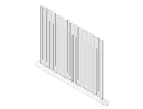
An ISO A1 construction drawing was also created for the flocculator and a similar drawing was released for construction.
Clear corrugated plastic, with 0.7 cm by 1 cm channels, was chosen to be used to build the flow channels due to its lightweight and ease of construction. The bottom of the flocculator was made from a 1 inch diameter acrylic rod. Stands for the flocculator was made out of acrylic slabs.
A sheet of corrugated plastic with the required number of channels and the required height was cut out from a larger stock sheet. Corrugations were cut out using a chisel and pliers, to connect the flow channels according to design.
The acrylic rod was milled flat on one side to accept the corrugated plastic. A channel was also drilled into one end of the rod to form the channel joining the flocculator and the sedimentation tank. Two shallow grooves are cut into the same end of the rod for the sealing O-rings.
The corrugated plastic and the acrylic rod was joint using acrylic bonding agent and air dried. Any leaks were sealed with glue. Rubber O-rings were then fitted onto the grooves.
The stands for the flocculator were made by drilling 1 inch holes in thin acrylic slabs. A hole was then tapped from the top of each stand to allow a thumb screw to be inserted to keep the flocculator from rotating arond the acrylic rod bottom.
Most construction work was performed by Paul Charles of the Civil and Environmental Engineering Machine Shop.
Picture of Flocculator.