You are viewing an old version of this page. View the current version.
Compare with Current
View Page History
« Previous
Version 19
Next »
Rapid Mix Tube Design Modifications
Agalteca Rapid Mix Tube Design Modifications
Please note: This page only describes and documents the changes and modifications that were made to the Rapid Mix Tube design for the customization of the Rapid Mix tube to the Agalteca plant. To view the original design parameters and theory behind the tube design, please see the original Rapid Mix Tube Design page. The theory behind the design is detailed here, including the design of the macro and micro scale mixing orifices, and parameters such as flow rate, energy dissipation, and target head losses are also included.
The Rapid Mix Tube designed during the Fall 2009 semester was installed in the new Agalteca plant in March 2010. The original Rapid Mix Tube design was very general, and certain modifications had to be made to customize the tube to the Agalteca plant. A second, modified MathCAD file was created for the Agalteca plant to serve a few different purposes:
- We need to be able to adjust the total head loss through the entire plant to adjust for any extra head loss created in the plant. The easiest way to do this is to change the number of orifices in the Rapid Mix Plate: adding more orifices will reduce the total amount of head loss, and creating a plate with fewer orifices will increase the total head loss through the plant. The MathCAD file created allows the user to easily input the existing plant parameters such as plant flow and measured head loss, as well as the existing plate characteristics, including the number and diameter of the existing orifices. Using this data, the MathCAD file calculates the total head loss created through the current plate, as well as the target head loss through the plant, and produces the number of extra orifices that must be drilled or taken away from the existing plate to achieve the target head loss through the plant.
- We also need to measure the head loss through the flocculator in the Agalteca plant, and the MathCAD file produced will also estimate that given the total measured head loss through the plant. Because the head loss through all other plant components can be measured or easily modeled, the head loss through the flocculator simply becomes the difference between the total plant head loss and the sum of the head losses of all other plant components.
- The target head loss through the plant will change with varying flow rates, so to adjust correctly the number of orifices in the Rapid Mix Plate, we must know the target head loss through the plant at the time of measurement. This calculation was also added to the MathCAD file for greater accuracy.
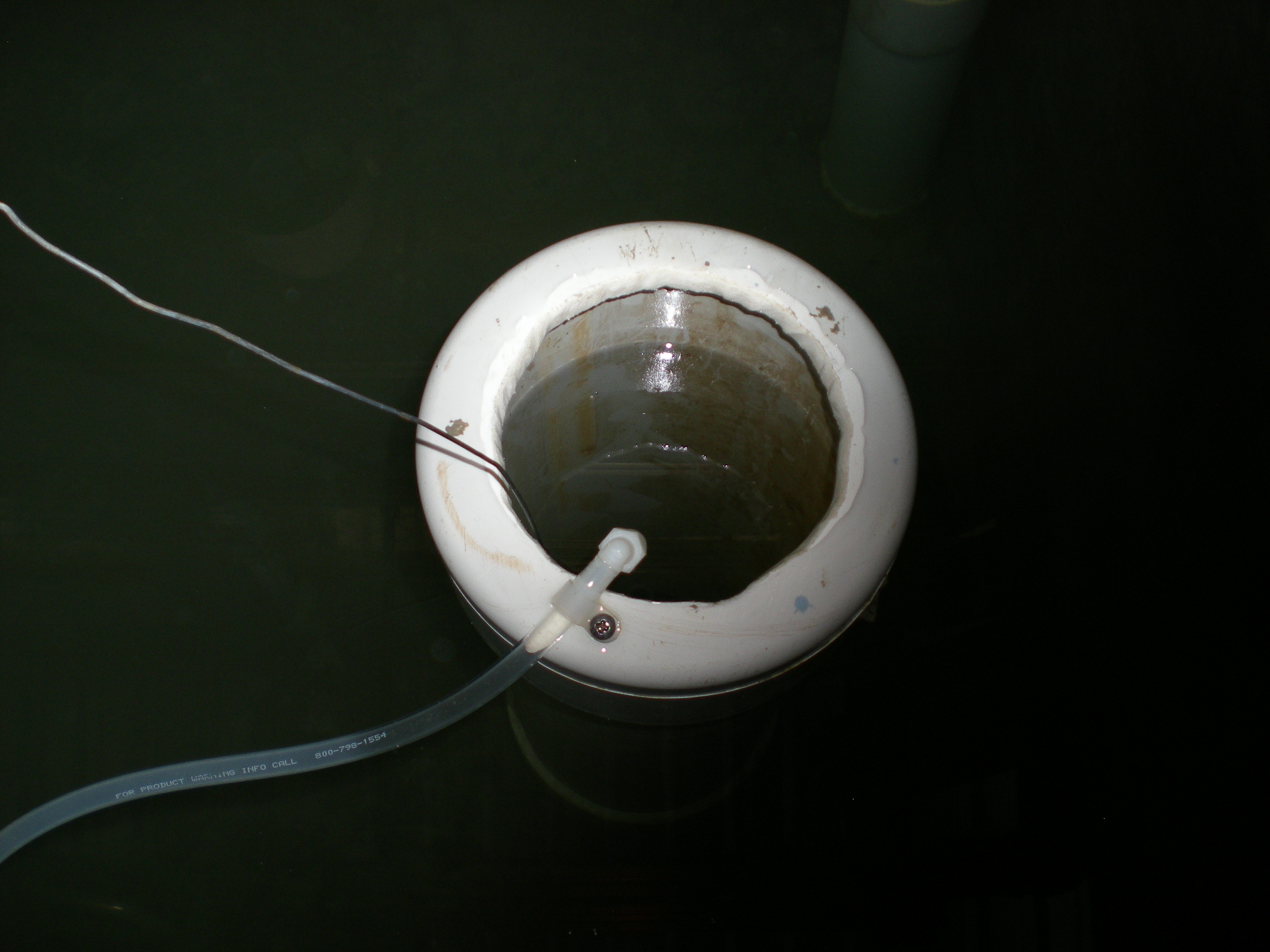
Another detail that was addressed in the Agalteca Rapid Mix Tube installation was the delivery of the dosed alum into the Rapid Mix Tube itself. To accomplish this delivery, the end of the flexible tubing running off of the doser's level arm was fitted with a small plastic elbow, then attached to the edge of the large scale mixing orifice using a small plastic clip. This allows the alum to be delivered directly into the flow of water entering the tube, improving mixing and reducing the chance that alum will escape into the entrance tank.
Deliverables
- Modified MathCAD file to achieve target head loss using rapid mix plate adjustments
- This MathCAD file is used to adjust the rapid mix plate orifice number and sizing to create the target head loss through the plant. It can also estimate the head loss through the flocculator, a variable of interest, as well as adjust the allowable orifice sizes for the rapid mix plate based on the actual maximum flow rates for the plant, which likely differ from those estimated for the design.

 user-1194e, last updated on May 05, 2010
3 minute read
user-1194e, last updated on May 05, 2010
3 minute read