*** This version of Confluence is for testing only and contains a copy of content from June 29th 2026. No changes will be preserved. ***

 user-dd1ec, last updated on Sep 06, 2008
9 minute read
user-dd1ec, last updated on Sep 06, 2008
9 minute read
Experiments run in fall 2007 have indicated that the float valve can hold back head of at least 8m with less than 0.5cm of change occurring in the flow controller water level in the first 2m of pressure. In field tests in Honduras the flow controllers have not been dosing as expected, which current lab work is aiming to correct. Data gathered in the laboratory on outflow rate has followed a linear model in the laminar flow range, but attempts to model the turbulent transition range have produced varying results. It is considered a high priority to develop a reliable model for dosing at higher flow rates, which will be used in the near future at the larger plant in Marcala, currently under construction.
Keywords: Flow Controller, laminar flow, height of outflow, influent pressure, float valve
Constructing reliable and cost-effective solutions for water treatment in Honduras is challenging due to the lack of infrastructure. Electricity is unreliable, which has rendered modern computer-automated water treatment plants unusable, moreover the mountainous terrain sometimes makes access to materials needed for construction or repairs difficult. While it does isolate villages and their utilities, the rough topography has created an opportunity for the use of gravity-powered treatment plants. There has been success with the implementation of AguaClara researched and designed flocculators that are mixed by gravitationally-derived kinetic energy, but chemical dosing in these plants without the use of electric pumps is still inconsistent.
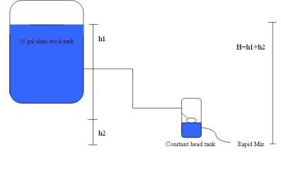
Alum, which is used in aiding flocculation, must be injected into the system during the rapid mix before influent water enters the flocculator. The concentration of alum required is dependant on the initial turbidity of incoming water, which is heavily dependant on local weather conditions and therefore subject to change. Alum is stored in a 55 gal stock tank, which feeds into the flow controller designed by AguaClara in the summer of 2007. A small plastic manufactured float valve maintains a nearly constant volume of alum in the flow controller. The flow rate of alum out of the flow controller is regulated by head loss in the outflow tubing (h2 in Figure 1). The outflow tubing connects directly into the rapid mix unit, with an adjustable connection so that plant operators can manipulate head loss. By changing the height at which the outflow tubing is connected to the rapid mix, alum dosing can be controlled without the use of a motorized pump or computerized control system.
! 
Plastic bottle flow controllers have been used in Honduras for alum and chlorine dosing for several months now, and a few problems have arisen. They have been clogging and the head loss to alum dosing relationship does not appear linear. Further testing this fall has been done with more precise equipment and an extra connector was removed from the flow controller to make it resemble the set up used in Honduras. The outflow to head loss relationship once again appears relatively linear in the laminar range, and it is possible that a different type of experiment should be designed to address the non-linear data from Honduras.
Other aspects of flow controller performance have also been tested this fall, including maximum inlet head allowable, water level variation in the flow controller, and corrosion resistance of the manufactured float valves. There have also been updates made to the materials used in the flow controller design.
Float valve corrosion test methods
Flow controller body design and selection
Flow versus head loss data collection in the laminar range methods
Flow versus head loss data collection in the turbulent range methods
The maximum inlet pressure that the float valve can shut off was investigated in order to determine how much head there can be between the chemical stock tanks and the flow controllers. A peristaltic pump was connected to the inlet of the flow controller, along with a pressure sensor. The outlet tube of the flow controller was plugged. The peristaltic pump was then used to pump water into the flow controller. The pressure of the water in the inlet tube, or the pressure the float valve could resist, was then measured using process controller. The maximum inlet pressure was determined using three orientations, with the float straight down giving the lever arm a 90 degree angle, partially down for a 45 degree angle, and straight out at zero degrees. This was to determine which orientation provided the greatest resistance. The pressure was also measured as a function of the height of the water level inside the flow controller. This relationship was determined for each of the different orientations by marking the water level in the flow controller at random intervals while simultaneously inserting a text flag in the Process Controller data. The text comments allowed us to show what the exact pressure was for the corresponding flow controller water level.
This data was analyzed in Excel to determine maximum shut-off pressures and change in flow controller water levels. The data for each float angle orientation was analyzed separately to determine an ideal angle to use in the AguaClara plants. The data was also manipulated to see if the water level in the flow controller would vary greatly enough to significantly impair flow controller function as a stock tank would drain in a plant.
Inlet Shut-Off Pressure Test Results
The corrosion test was conducted for five weeks. There was no visible corrosion to the float valve screw, pad or pin in the alum solution. After a week, the float valve placed in the chlorine solution had severe visible corrosion of the screw, but no visible corrosion of the float valve pin or pad in the chlorine solution. Although the chlorine and alum solutions were replaced every week to maintain reactivity, we were uncertain of how reliable this data would be. The flow controllers in place in Honduras are continually supplied with fresh chemicals and they are constantly monitored, so we are deferring data collection on float valve corrosion to the plant operators and engineers in Honduras.
The maximum inlet pressure that the float valve could resist was determined. Float orientations of 90, 45 and zero degrees all resisted a pressure of at least 8m. A float orientation of zero degrees resisted pressures of at least 11m. All of the float orientations have a maximum inlet pressure well above the 2m needed for the AguaClara plants.
This data was further analyzed to also determine the amount of variation in flow controller level with increasing pressure build up on the float valve.
The level in the module changed by many centimeters during the experiment, but this was over the entire range of inlet pressure build-up. For the range that is pertinent for designing AguaClara plants, up to at most 2m, the level changed in the flow controller much less. The table below shows the total change in flow controller water level at both the highest back pressure reached, and at approximately 2m of pressure.
|
0 Degrees Float Angle |
45 Degrees Float |
90 Degrees Float |
|---|---|---|---|
Water Level Change at 2m Pressure |
1.2 cm |
0.4 cm |
0.35 cm |
Total Water Level Change |
2.4 cm |
1.2 cm |
0.9 cm |
Positioning the float straight out from the valve caused the most variation in water level, while positioning it at an angle of 45 degrees or 90 degrees had about the same effect. Currently the floats are positioned at an angle somewhere between 45 degrees and 90 degrees to best fit inside a small flow controller. Assuming this positioning is kept, the variation in water level is large enough to influence the outflow by effectively causing error in the expected head loss in the system of up to 0.4cm. While this does create a discrepancy between assumed and actual head loss in the system, it is much smaller than the uncertainty caused by a draining stock tank.
Inlet Shut-Off Pressure Procedures
Through this semester the Flow Control Module testing apparatus has evolved to allow more precise testing to take place. The next upgrade to our testing equipment is an automated position control, which will be capable of changing the head loss in the system automatically. This will increase the precision and quantity of data collected in the future.
With the current equipment we have begun to characterize the outflow from the flow controller in both laminar and turbulent flow ranges, while experimentally showing that there is too much uncertainty in the transition region to effectively set simple dosing guidelines through it. The maximum laminar flow rate for the flow controller was much lower than the dosing that will be required for the new water treatment plant in Marcala, which poses a challenge for us. The easiest route may be to use several flow controllers in parallel to deliver the necessary chemicals to the plant, or modeling the flow controller for the turbulent range may show that one flow controller alone could reliably deliver enough outflow to meet the plant's demand. Other options for increasing alum dosing with the given head loss available in the system would be to increase the strength of the alum stock, necessitating a lower flow rate, or decrease the length of the flow controller outflow tubing. These options should be investigated further to compare the cost of materials and the reliability of operating in the turbulent range. This work will help to characterize the flow controller technology for use in higher volume water treatment plants as well as those it was originally designed for.
To determine the amount of modification required to increase flow controller flow rate, we would need accurate values for the kinematic viscosity of chlorine used in the AguaClara plants. Doing online research and contacting manufacturers provided little useful information, and the viscosity may need to be determined experimentally. This would involve running two tests: an outflow to delta h test with water and an outflow to delta h test with chlorine. The ratio of the outflows is then equal to the ratio of kinematic viscosities for water and chlorine. This testing should probably be done in the next semester.
Now that a few comprehensive data sets have been collected with the latest equipment, a new dosing chart can be made for Honduran plant operators. As this data was collected without the barbed connector in place, it should provide a better model for their systems. When the new fully automated experimental set-up is available it should be used to collect the most precise data set so far, which can be used to further refine the plant operator dosing chart from what has been established this semester. This equipment will ideally be able to produce consistent data in the turbulent range, where our data sets thus far have been showing conflicting results.
To test the flow controller in a real use setting it may be useful to tie it into the pilot system at the Cornell Water Treatment Plant (CUWTP). The flow controller could be tied into the system between the alum stock tank and the rapid mix, where it would be installed in a full-sized AguaClara plant. This set up could be used to gather qualitative data on the flow controller performance when it is left to run for extended periods of time, not just 30 second intervals. There were various problems in Honduras with alum sediment collecting in the flow controller, and occasionally clogging the float valve. While some of the original operating problems have been overcome, there are still shortcomings that we should be able to assess and observe in person.