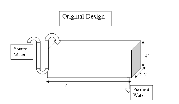
Figure 1: Rough Schematic of existing structure
The Linear Orifice Flow Meter was tested and compared to the results expcted from a traditional sutro wier. The steps of the experiment and th results are available below. The experiment showed a very low deviation from the predicted.
Figure 1: Rough Schematic of existing structure
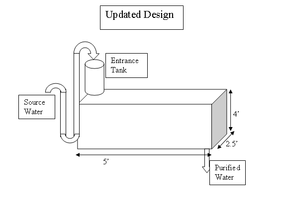
Figure 2: Design including the linearized flow tank
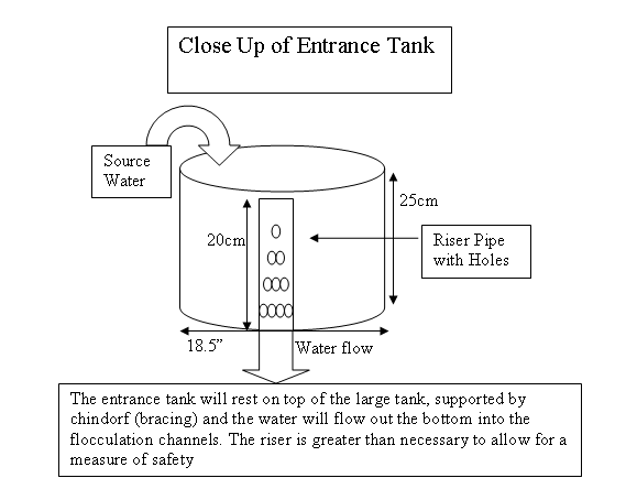
Figure 3: A close up of the linearized flow tank
Attached is an excel spread sheet checking the various riser pipe diameters for the entrance tank.
Since the existing PVC pipe that brings the water in is 3" I will use the 3" pipe to construct the riser pipe. Checking with the program the 3" will be more than big enough to accomodate the holes. the holes necessary for the riser pipe were found using the mathcad program developed by David Railsback for linear flow. After Talking with Tom at the water treatment plant I think i will use a 5 gallon bucket. It would be relatively easy to outfit the bucket with a toilet flange on the bottom of the bucket that the riser pipe can slide into. My earlier worries about the size of the entrance tank were unfounded because it turns out that the area of the entrance tank doesn't matter only the height of the tank.
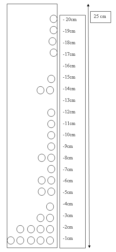
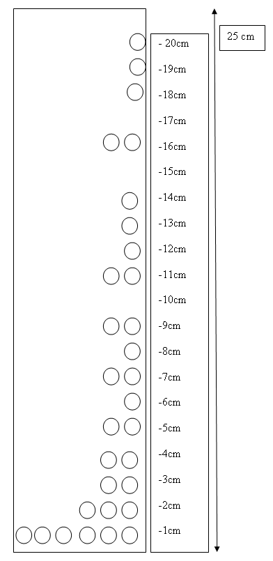
Figure 4: A close up view of the riser pipe with the necessary holes. As a note the diameter of the holes is 3/8 inches. The tube on the left is designed with a max flow rate of 120 L/min and the pipe on the right has a max flow rate of 125 L/min
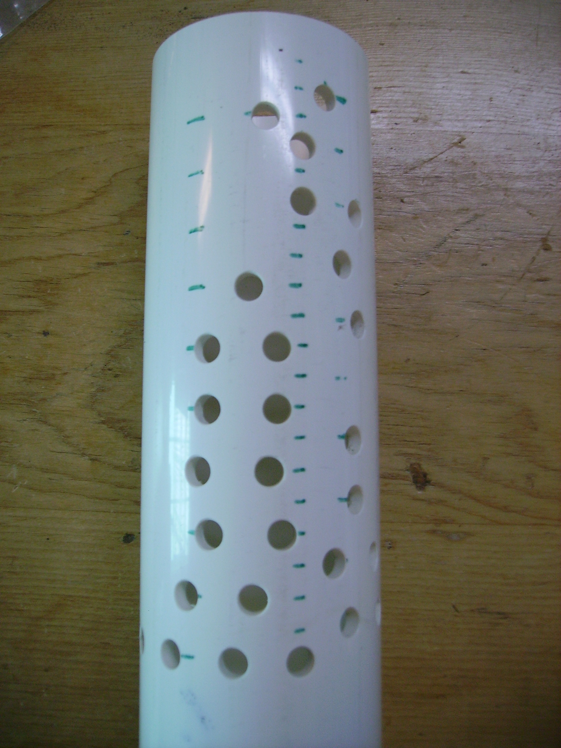
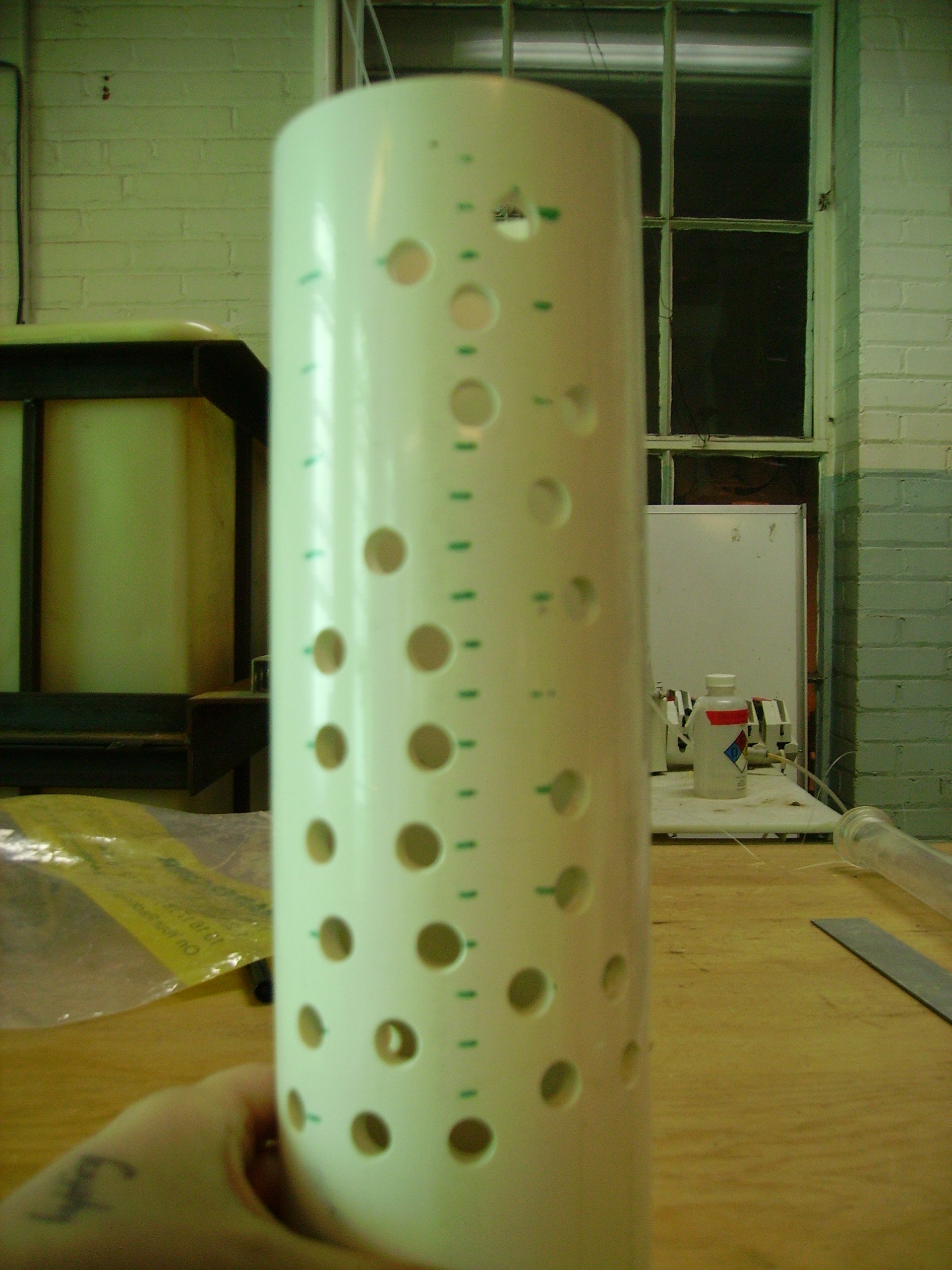
Figure 5: Actual photograph of the riser pipe
Item |
Amount Necessary |
Price |
|---|---|---|
5 gallon pale, transparent |
1 |
$5 |
3" PVC Pipe |
4.1' |
$16.64 for 8' |
toilet flange |
1 |
$3 |
stainledd steel screw |
4 |
$2.00 |
Bracing |
Not sure |
Tom willing to help and provide materials |
Total: ~$18.00
#I decided to cut the holes on the pipe for a maximum flow of 125 L/min (the actual max is 120 L/min) so that there would be some wiggle room.
#An extra piece of tubing was used underneath the bucket to add extra length and mitigate the spashing and spilling that originally occured.
Note: I have stopped by several times over the past couple of weeks to work with tom to help install the bucket and the flow control device and it seems to be taking much longer than i had originally anticipated. The Bucket is comletely installed on March 13th.
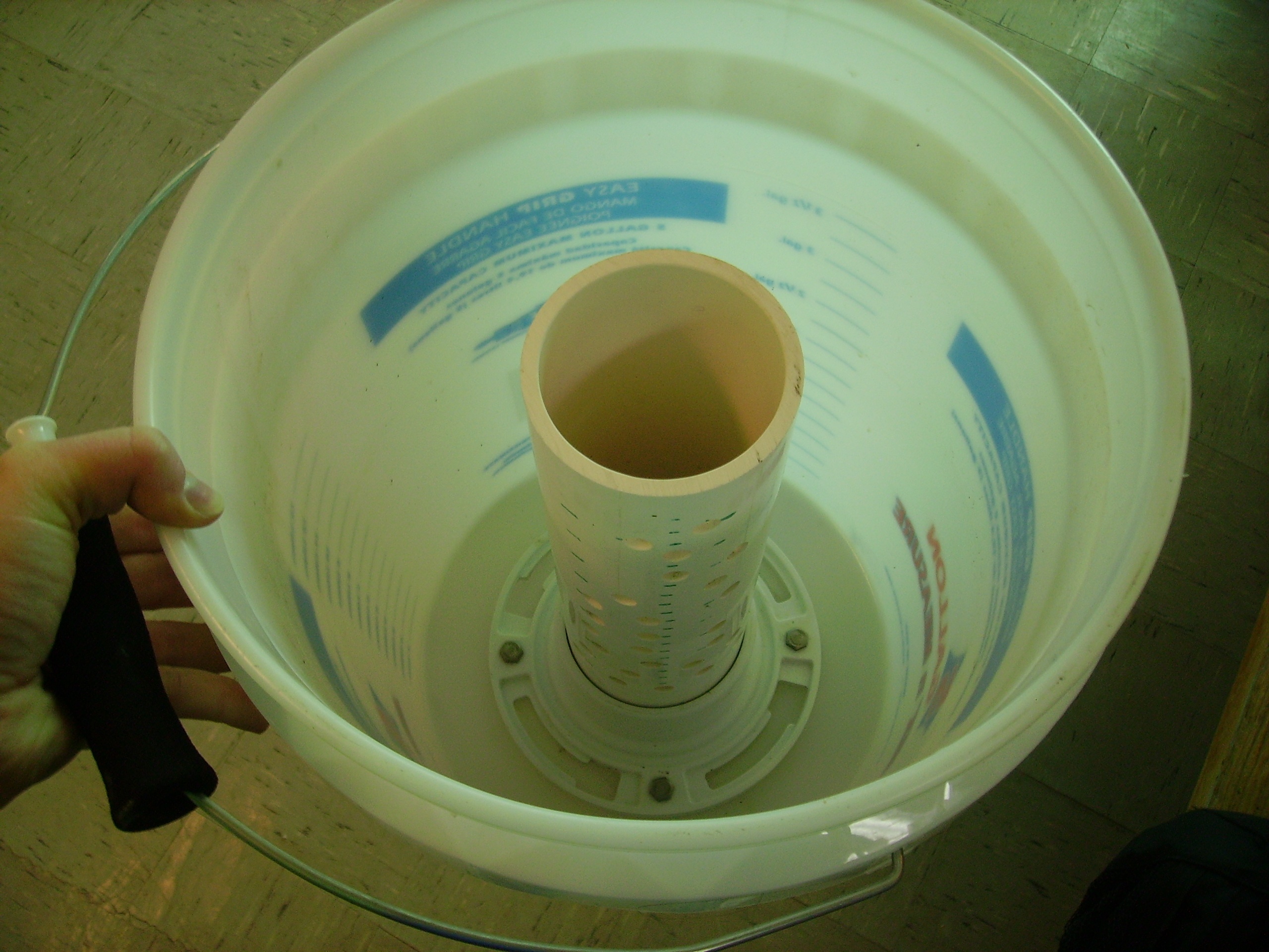
Figure 6: close up of completed bucket
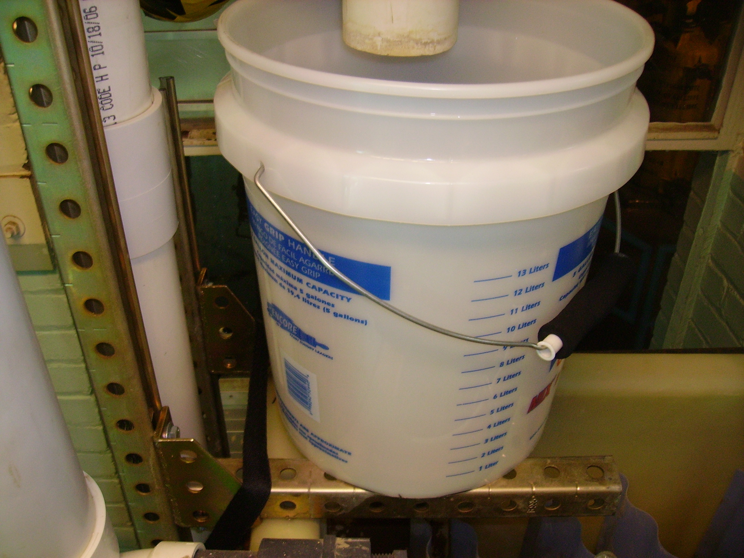
Figure 7: Completed bucket installed in pilot plant
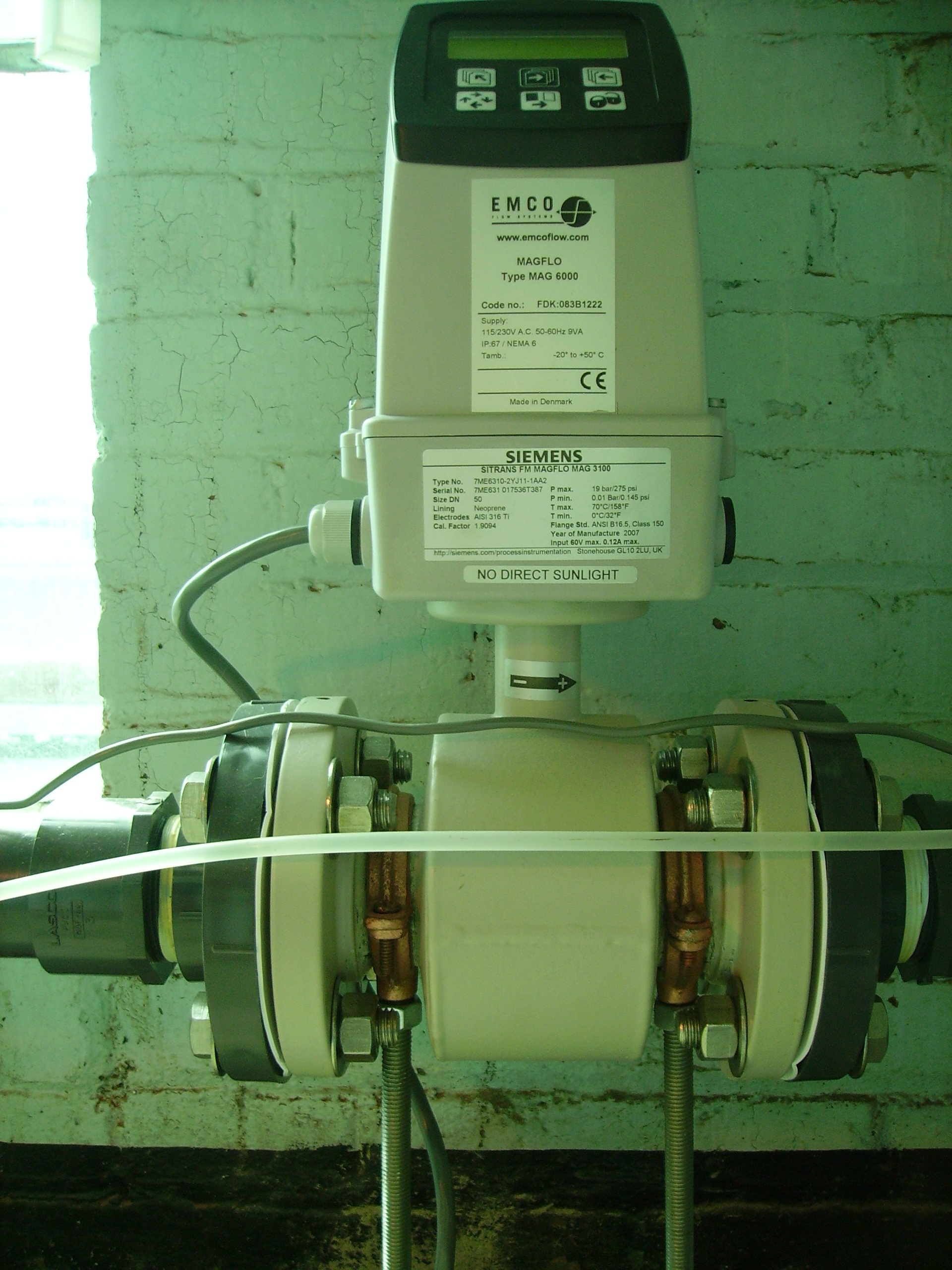
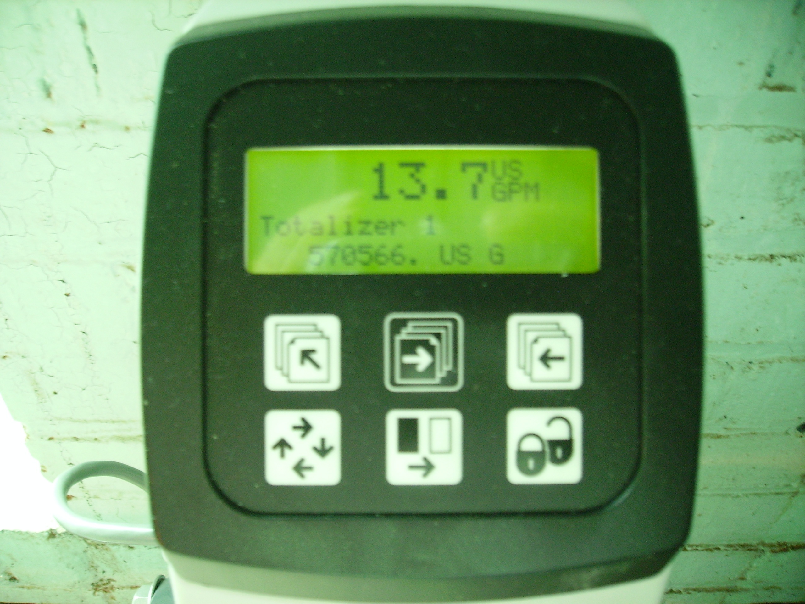
The entrance tank with riser pipe was installed in the plant and measurements were taken on the efficiency and accuracy of the design. There is an in-line flow meter that will provide flow rate data that can be compared to the flow rate recorded based on height in the entrance tank. There will be readings at incremental flow rates where the machine flow rate and water height will be recorded.
1) Check that ALL holes are clean and free of obstructions
2) Record the flow rate from the flow meter in GPM
3) Record the height of the water in the bucket using a ruler (inches), be sure to place the end of the ruler on the edge to ensure contact with the actual bucket base. the pictures below show the techniques for recording water height.
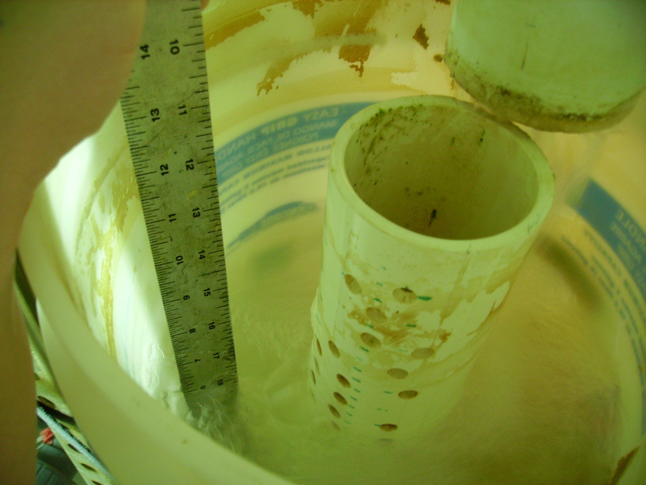
4) For next reading change the flow rate manually and then wait approximately 5 minutes for the flow to acclimate.
5) Record the stabilized flow rate and the water height.
SO when i acidentally redirected this page to another website through a mistake in programming Aaron Hamid helped me out. In order to undo the problem he determined the pageId of the page by using the page-info macro on a different page, and then manually entered the page edit url (https://confluence.cornell.edu/pages/editpage.action?pageId=79299719) to edit the page and remove the redirect.