CFD Flocculation Tank Simulation goals and meeting minutes.
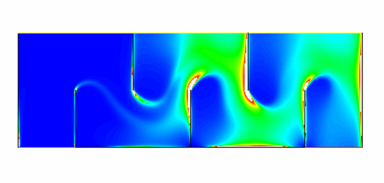
Little information is available about the fluid behavior within the flocculation. The flow is turbulent and involves separation, reattachment, and high shear. Our team uses CFD simulation to predict velocity gradients, pressure losses and energy dissipation rate in the flocculation tank. By varying geometric configurations, and analyzing the resulting energy dissipation rates, the design of the flocculation tank can be optimized. Below is the energy dissipation rate for the a five baffle flocculator with a height to baffle spacing ratio of 2, and a clearance height to baffle spacing ratio of 1.
CFD Flocculation Tank Simulation goals and meeting minutes.
CFD Analysis of Flocculation Tank and Design Recommendations
Examines the back-step example to determine the type of turbulence model to use in FLUENT.
Determines the Gθ value for various flocculation height (fh) to baffle spacing (bs) ratios using a UDF in FLUENT.
Examines the affect of varying the velocity inlet from .1 m/s which corresponds to a Re=10,000 to 1 m/s (Re=100,000) and .01 m/s (Re=1,000).
Examines the affect of varying the turbulent inlet length scale for the optimal geometry.
Determines the optimal geometry for the flocculation tank by varying the fh/bs, and ch/bs ratios.
Determines the optimal fh/bs ratio for the flocculation tank height by comparing performance parameters which quantify flocculation collision potential.
Examines the energy dissipation profile for varying fh/bs ratios, and how there is a local maximum for smaller fh/bs flocculation tanks.