Chemical Dose Controller History
By far, the biggest hurdle in the development of AguaClara technology has been devising a method for accurately and precisely administering process chemicals while adhering to the fundamental AguaClara design constraint of creating solutions which do not rely on electricity. Modern water treatment plants have computerized control and precise metering pumps at their disposal and while an AguaClara engineer has neither of these, this does not diminish the need for accurate metering.
To that end, AguaClara engineers have been developing a Chemical Dose Controller (CDC) which utilizes principles such as gravity, differences in head pressure, major losses in pipes, etc. to predictably meter process chemicals. The first CDC developed by AguaClara engineers was the Linear Dose Controller, named so because of the linear relationship that exists between flow and the head-loss that occurs as fluid flows through a pipe. This was a simple design that utilized the predictable major head-loss which occurs in a small diameter pipe to meter the flow, and therefore the chemicals, administered to the plant. This relation only holds true under laminar flow conditions and therefore fails as plants increase in size because the required increase in chemical delivery rate causes the fluid to enter the turbulent range.
To overcome this, AguaClara engineers are developing a CDC that utilizes the head-loss through an orifice (rather than through a pipe) to meter the flow of process chemicals. This is the Non-Linear Dose Controller, so-called because flow is now a function of the square-root of the height differential, making the relationship non-linear.
Current State of the Nonlinear Dose Controller
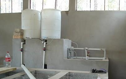
The AguaClara engineers from academic year 2009/10 not only designed, but built and installed a Non-linear Dose Controller (NDC) in a new AguaClara plant in Algateca, Honduras. The current NDC is installed on top of the entrance tank of the plant and consists of a float connected to one end of a lever arm and the dosing orifice connected to the other end.
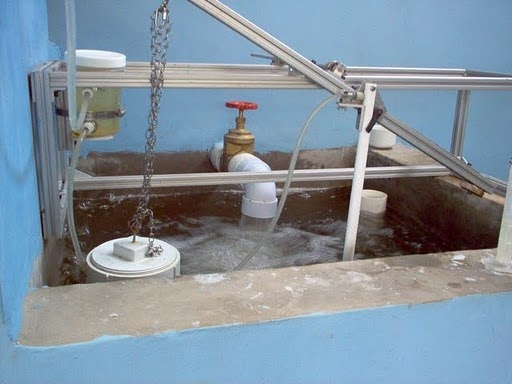
The entrance tank is connected to the hydraulic flocculator by way of a rapid mix orifice. A change in flow rate through the plant is indicated by a change in the level of the entrance tank. This is transmitted to the lever arm by way of the float. For example, if the flow rate of the plant were to decrease from 100% to 80%, the entrance tank would drop by a proportional amount. Since the pivot is in the center of the lever arm each centimeter of change in the entrance tank will correspond to a centimeter of change in the heights of both ends of the height of the lever arm (although, obviously, the two ends will be moving in opposite directions).
Alum is piped from a 120 g/L concentration stock tank to a constant head tank and from there to the metering orifice. The metering orifice is connected to the lever arm by way of a movable slide. The lever arm has an incremental scale on the top surface which corresponds to specific alum concentrations. The operator is able to set the chemical dose concentration according to the values on the scale and the lever arm will automatically adjust the flow rate of alum to maintain the correct concentration of alum as plant flow rates change.
Feed back from operators and engineers in Honduras along with results from our own experimental lab work provide us valuable information on the accuracy and ease of operation of the NDC. Additionally, brainstorming continues on how to improve and expand the function of the current design. Derived from these topics are the following recommendations for next semester's team.
Recommended Work for Fall 2010
Orifice Validation and Scale Development 2 - 4 Persons
One of the priorities of AguaClara engineers is to ensure their designs are locally sustainable. It is easy to create the walls and foundations from locally manufactured materials but becomes increasingly difficult when very specific components are needed to perform very specific tasks. This proved true with the float valve used in the constant-head tank and may prove true with a metering orifice. The team that originally developed the NDC was not able to fabricate precise (e.g. repeatable) orifices for their lab tests. This team also noted that surface tension effected accuracy of a metering orifice when less than 4 cm of head was available. The Summer 2010 team concentrated on documenting the extent of the precision problem and researched various solutions. It is the belief of the Summer 2010 team that we can not properly quantify the inaccuracies associated with surface tension until the material and manufacturing techniques are finalized since material finish, or smoothness, has a strong influence on surface tension.
The parameters for a metering orifice that adhere to the guidelines set forth in the AguaClara Mission Statement are:
- The orifice must be made from a material that is impervious to all process chemicals that are used or will be used in the future in an AguaClara plant. This includes alum, chlorine and saturated lime.
- The material selected must also have certain machinable characteristics. Initial attempts at fabricating the orifice from plastic "quick connect" caps proved fruitless. These plastics do not machine well and produce unreliable metering between orifices of the same size.
- It it preferred that the orifice be manufactured from "commonly available" fittings of a "commonly available" material, particularly one that would be available in the communities/countries we service. Correctly defining "commonly available" is part of this challenge.
The Summer 2010 Team attempted to determine if it was reasonable to expect that a precise metering orifice could be fabricated in-house. The extent of this research is documented on the team's wiki pages, however, a few key lessons-learned are summarized below.
- Acetal and Polyamide plastics are not suitable materials for producing precisely machined orifices. These materials do not "chip" but instead heat-up and deform. This leads to a slight collapse of material around the orifice hole as the drill bit is removed and marked deformation at drill-bit break-through. We attempted to correct for this by drilling in the direction of flow so the drill-bit break-though would occur at the exit region instead of the entrance region (which has a significant effect on the coefficient of discharge). This still did not produce acceptable results; 15 - 18% variance between orifices was measured.
- As metals possess better machinability characteristics than plastics, two styles of brass caps were selected for review. Admittedly, brass may not be the best choice for chemical compatibility (particularly chlorine), it is extremely machinable. Our thesis was that if we could not machine the parts from brass in-house, it would be unlikely to find a more suitable material from which we could. We selected brass refrigeration tubing caps and SAE flare caps. Our first trial showed similar variations between orifices meaning that we were not any more successful at machining precise orifices in-house We were still drilling in the direction of flow and determined that the centering bit created a different shaped entrance region in each cap, thereby changing the K.vc for each cap. The caps were then drilled against the direction of flow so the bevel created by the centering bit occurred at the exit region. Drilled brass does not create significant burrs at drill-bit break-through so the entrance region should be the fairly consistent between orifices.
*Less than 5% variance between brass caps which were drilled against the direction of flow was recorded, proving that we could indeed fabricate precise orifices in-house. The next step is to reproduce similar results with a material that is compatible with our process chemicals. At the time of this writing, the CDC Team was planning to machine orifices from solid PVC stock. Note, an engineer with Kerick Valves has explained that the orifices in these valves are created during the injection molding process and are not machined-in separately. He claimed that the process of injection molding produced much more repeatable results.
Thorough research of off-the-shelf orifices has not yet been completed. The Summer 2010 team investigated the use of carburetor jets as metering orifices and these results can be seen on their wiki page. Additionally, orifices can be found in many industrial applications such as paint sprayers, "line coolers" (jets of fluid used to cool parts in an assembly line) and burner jets, to name a few. These will be manufactured under more exacting standards than we could hope to replicate especially in the some of the remote areas where our plants are best suited. One manufacturer that needs further research is Bird Precision, maker of lab-grown ruby orifices. These orifices are impervious to chlorine and can be installed in virtually any style of fitting. Additionally, their orifices are fabricated by piercing a lab-grown ruby cylinder with a laser, followed by drawn wire. This results in the best surface finish possible which may help in mitigating the surface tension issues.
The importation of components, however, cannot be taken lightly. Although we have determined that it is possible to fabricate a fairly precise orifice in-house we have not yet done so with a material that is suitable for use with chlorine. The next step is to find a material that is not only suitable for use with our process chemicals but possesses the machinability characteristics that allow for repeatable fabrication of the orifice. Further, this component would then need to be readily available is the areas we service. As impossible as all this sounds, the success of an AguaClara plant would be greatly improved if an operator could easily replace any lost or damaged orifice by simply drilling an appropriately sized hole in a pipe cap.
Concluding, we need to select the component that will be used for the metering orifices in AguaClara plants. Once we determine and fabricate our orifices, we can then begin to quantify accuracy and surface tension issues.
Once a final decision has been made as to what material will be used for fabricating the orifice, the dosing scale will need to be developed. Again, because surface tension is directly related to material finish, fluid flow through a drilled PVC orifice is apt to behave quite differently than a laser pierced ruby. Fall 2009 developed a dual-scale, dual-orifice system. (link Mathcad file) This scale does not accommodate surface tension in anyway and therefore fails at low plant flow rates and low dosing concentration. Spring 2010 attempted to solve this problem with the development of the triple-scale, triple-orifice (link Mathcad file) This scale works well for all concentration ranges by starting the scale farther from the pivot point. However, at 50% plant flow rate, the head-loss through the plant is only 10 cm. We could easily enter the range where surface tension (depending of the material selected for the orifice) restricts flow at low concentrations of alum. The Summer 2010 team attempted to correct this by moving the float during periods of low flow so that a 4:1 relationship exists between plant flow and dose height. (link Mathcad file) . This solution maintains the dual-scale but does incorporate triple-orifice and requires an additional action from the operator.
One of the above listed scales or newly developed scale needs to be selected then coding developed so the Automated Design Tool can generate the scale template need for the CDC.