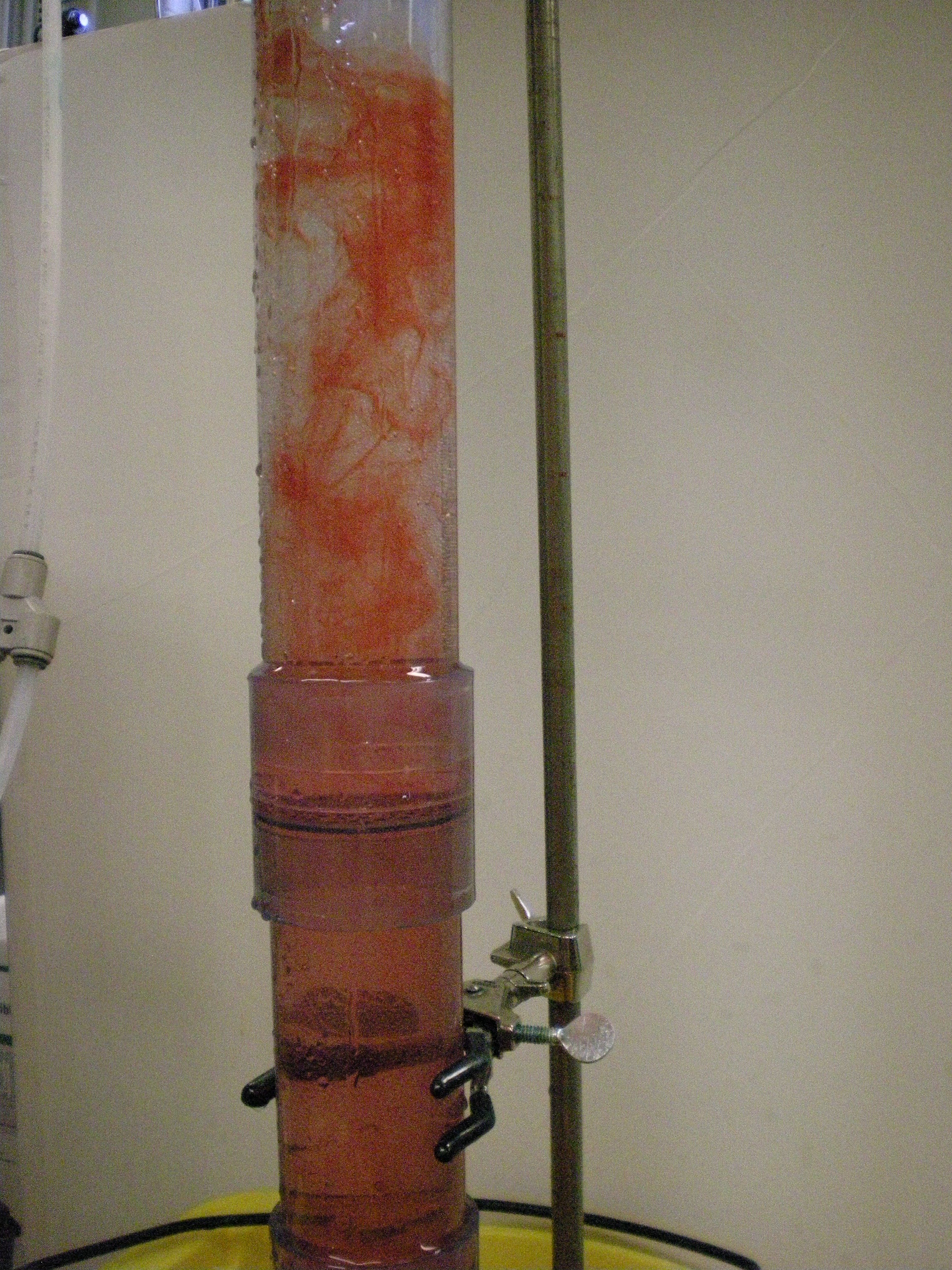
The Chemical Dose Controller team traveled to Washington, D.C. in April 2009 to compete for a Phase II grant in the EPA P3 competition. The rapid mix tube was designed under the chemical dose controller team and plays an important role in the dosing process, and was thus included in the EPA project proposal and was a part of the display at the competition. A scale version of the rapid mix tube developed in the Fall 2009 semester and refined in the Spring 2010 semester was developed to be taken to the conference and demonstrate the concept of rapid mix and how it relates to water treatment.
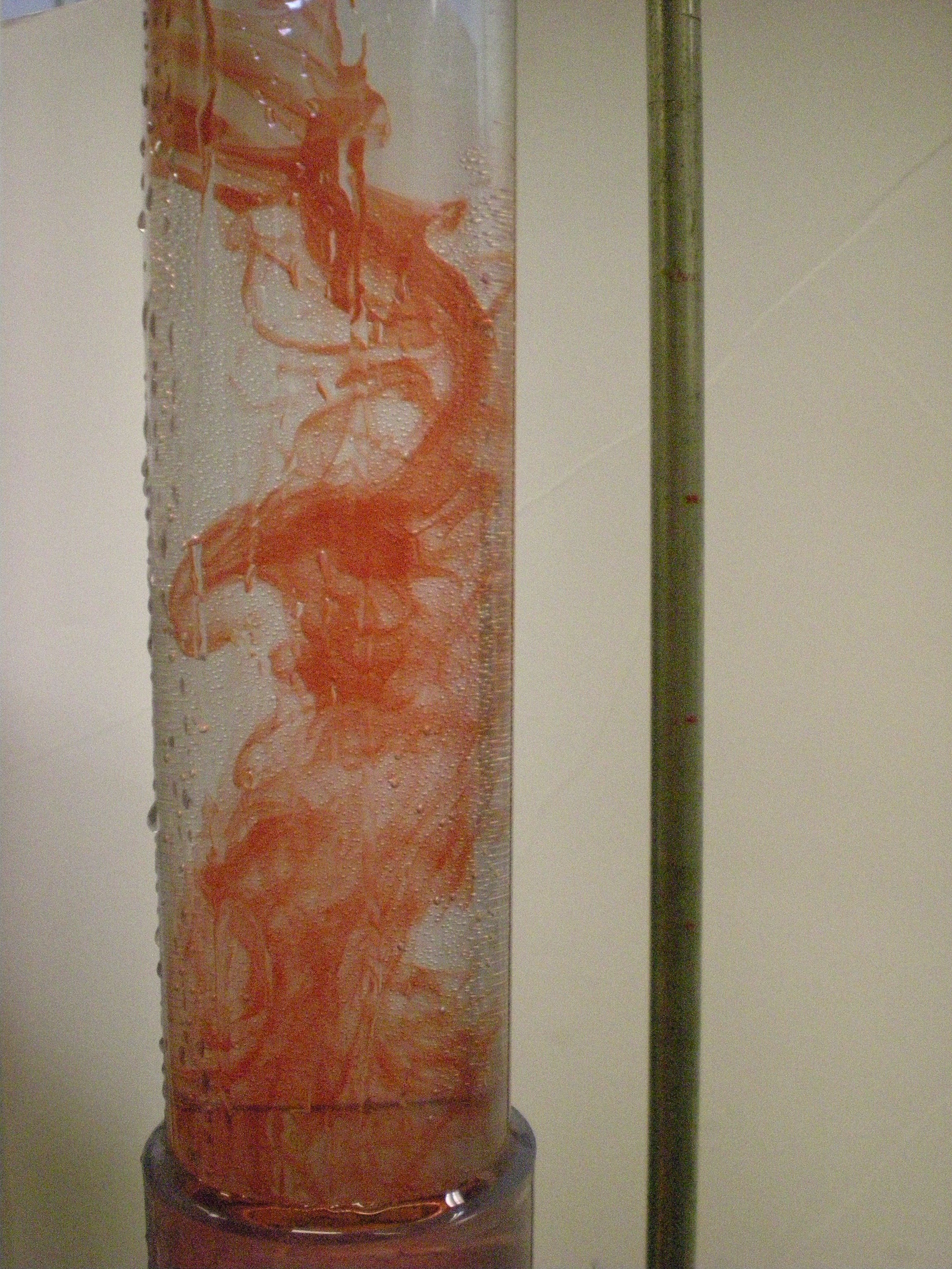
At the conference, the rapid mix tube display was run using a peristaltic pump to create flow through the apparatus. We also introduced Red Dye #40 into the water flow at the entrance to the rapid mix tube to simulate and visualize the mixing of alum and water that occurs in the rapid mix tube.
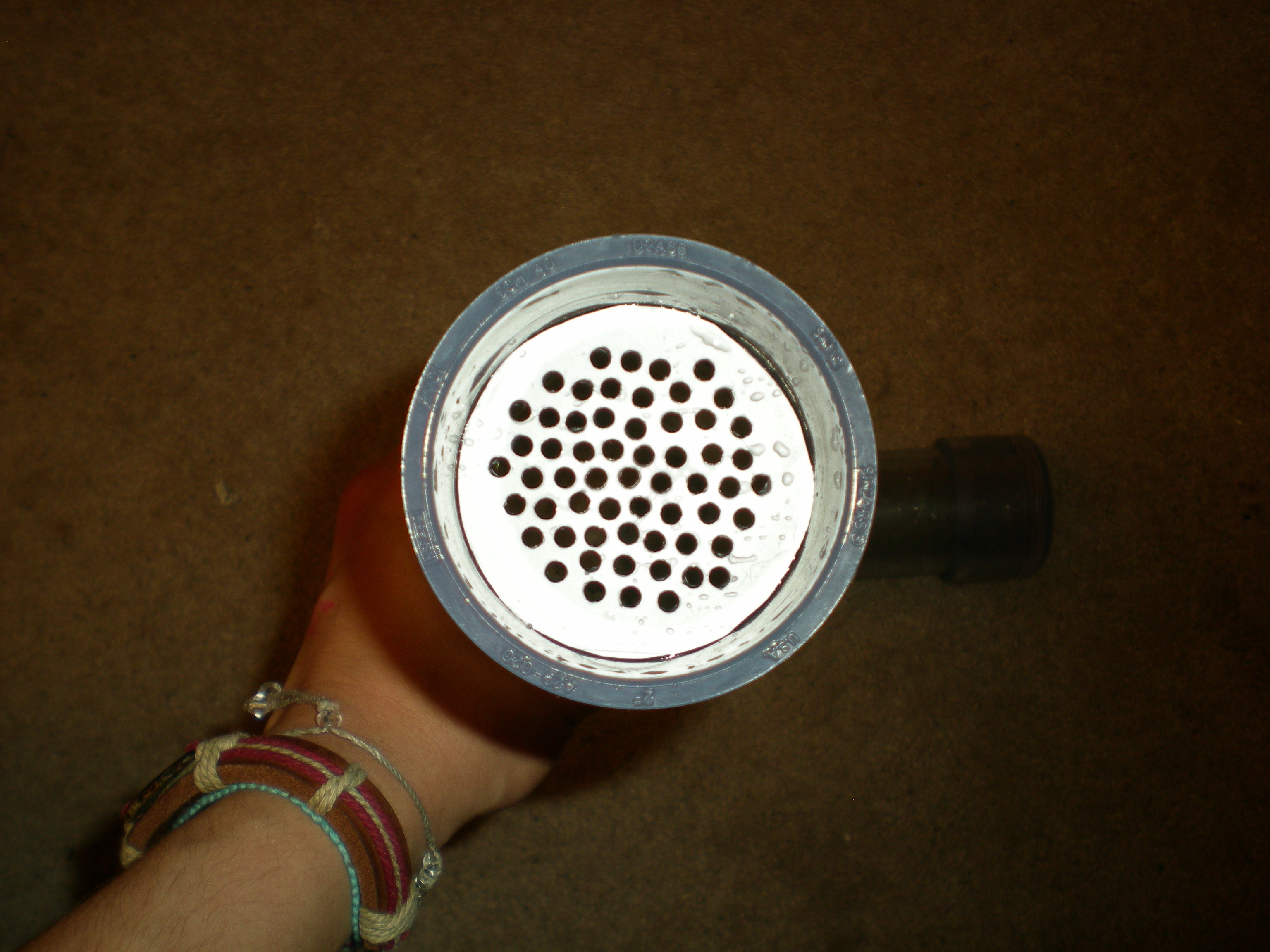
The design of th EPA scale rapid mix tube is almost exactly that developed for use in the AguaClara treatment plants, simply scaled down to provide a smaller tube and accommodate a smaller flow rate of water through the system. A separate MathCAD file was developed to provide a starting place for the full design of the EPA rapid mix tube. The flow rates of water through the tube, as well as the size and diameter of the tube itself have become mush smaller, requiring some adjustments to the original tube design. The most notable changes include:
It should be noted that, because the purpose of the scaled version is for display purposes only, the initial MathCAD parameters calculated for orifice sizes, flow rates, etc were used only as initial guides; the design was continually adjusted manually to provide a good visual display only (exaggerated version of the mixing processes), not to provide an accurate visual representation of what would be occurring under plant flow conditions. Therefore, design parameters were constantly altered and arbitrarily assigned during the building and testing process as pumps and flow rates and orifice sizes changed to create the best visual representation of the mixing processes for the competition.
For the true plant-flow design parameters, process, and conditions, please reference the full Rapid Mix Tube design page.
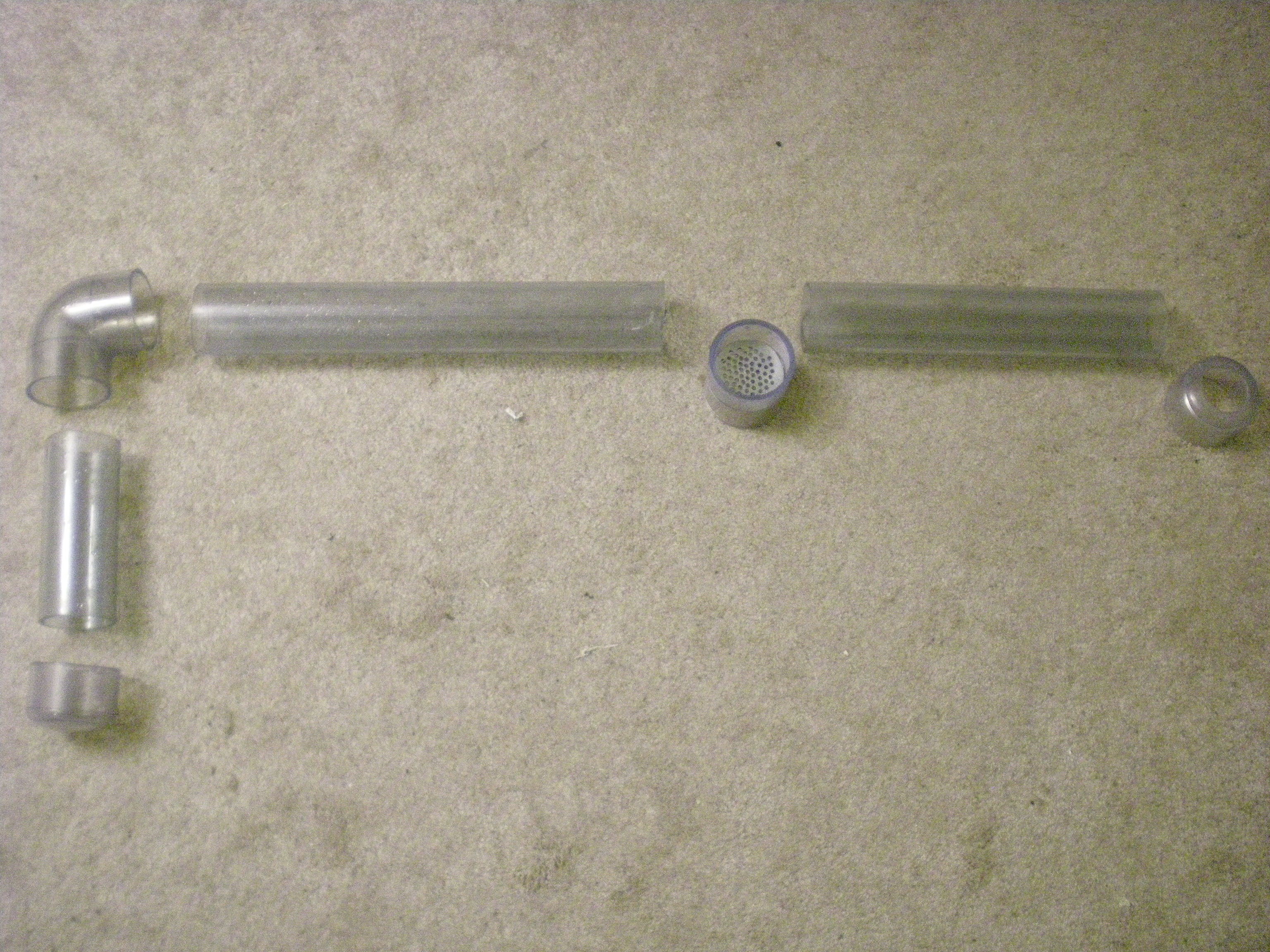
The scale model of the rapid mix tube was constructed out of clear PVC tubing to enable easier viewing of the rapid mix process in the tube.
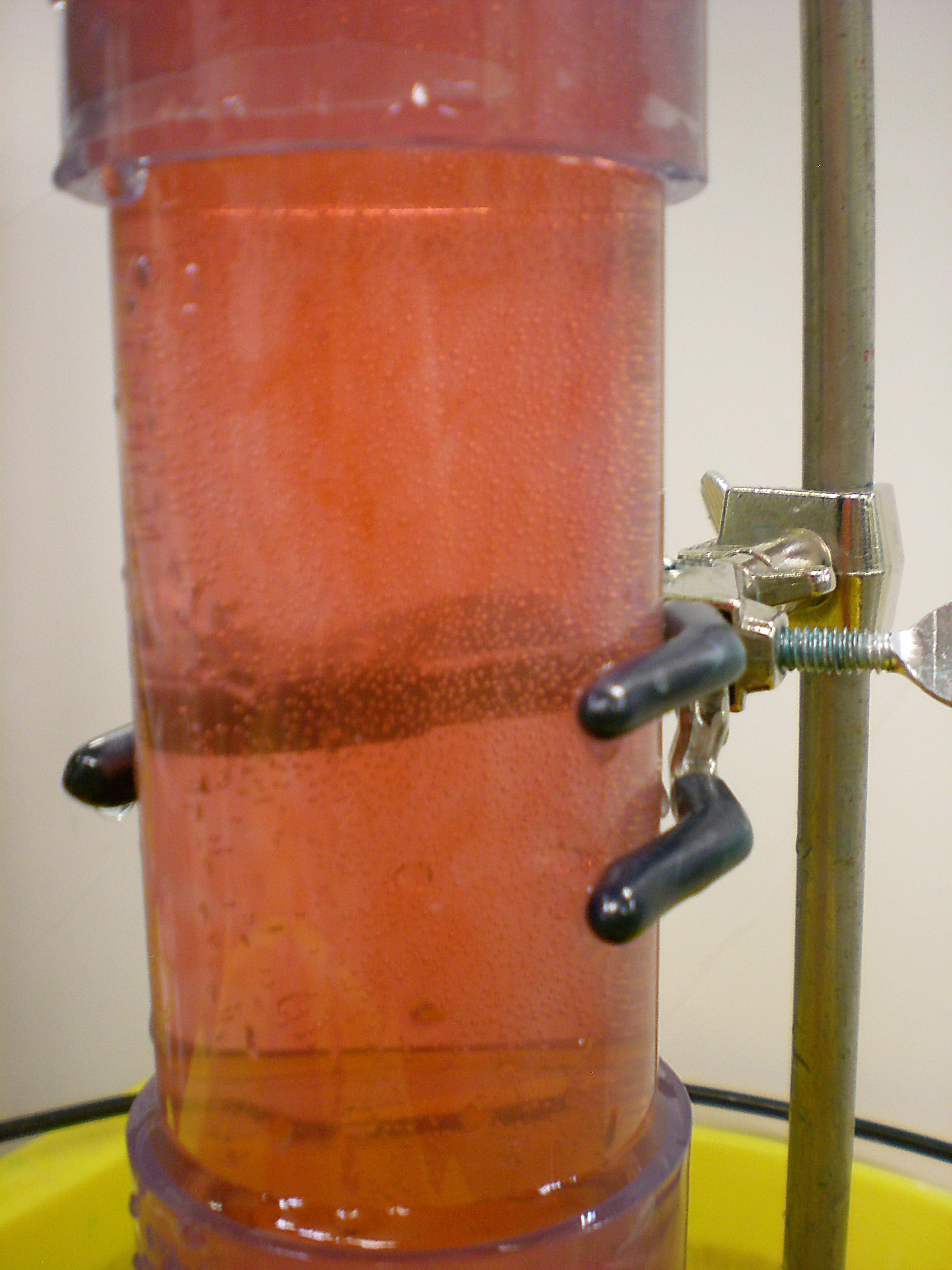
Experiments with the introduction of Red Dye #40 into the flow through the rapid mix tube were conducted throughout the Spring 2010 semester. The goal of these experiments is to provide a good visualization of the flow of the dye, which represents alum, through the tube, allowing us to see the different stages of flow and mixing of alum with the water in the rapid mix system.
Preliminary experiments indicated the need for an accumulation chamber to feed the rapid mix tube display in place of a direct pump line from the water source. A direct pump line feeding into the top of the rapid mix tube creates a lot of mixing in the upper portion of the tube, negating the visual effects of the display. Thus, to create a calmer, steadier flow into the rapid mix tube, we will introduce a chamber, directly fed by the pump line that will provide a steady flow into the rapid mix tube and allow for better visualization of the chemical mixing processes.
More dye experiments were performed through the remainder of the Spring 2010 semester leading up to the EPA conference. The following images and video were captured during one of these experiments. It should be noted that the flow of water and dye through the rapid mix display tube were altered to provide a good visual, conceptual effect for these demonstrations. When operating as designed in AguaClara plants, the alum (represented by the dye) will immediately appear dispersed throughout the upper portion of the tube following the macro-scale mixing orifice; this scale tube produces this uniform mixing immediately when run using the same parameters it would encounter in plant flow, however, only photos of the display parameters are shown here: