Please note: This page only describes and documents the changes and modifications that were made to the Rapid Mix Tube design for the customization of the Rapid Mix tube to the Agalteca plant. To view the original design parameters and theory behind the tube design, please see the original Rapid Mix Tube Design page. The theory behind the design is detailed here, including the design of the macro and micro scale mixing orifices, and parameters such as flow rate, energy dissipation, and target head losses are also included.
The Rapid Mix Tube designed during the Fall 2009 semester was installed in the new Agalteca plant in March 2010. The original Rapid Mix Tube design was very general, and certain modifications had to be made to customize the tube to the Agalteca plant. A second, modified MathCAD file was created for the Agalteca plant to serve a few different purposes:
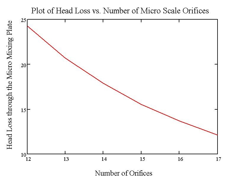
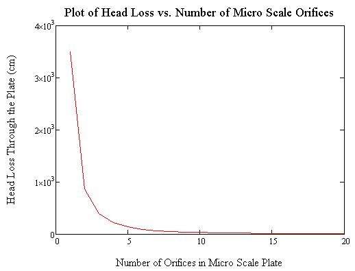
The MathCAD file created allows the user to easily input the existing plant parameters such as plant flow and measured head loss, as well as the existing plate characteristics, including the number and diameter of the existing orifices. Using this data, the MathCAD file calculates the total head loss created through the current plate, as well as the target head loss through the plant, and produces the number of extra orifices that must be drilled or taken away from the existing plate to achieve the target head loss through the plant.
The energy dissipation rate created through the micro scale mixing plate is dependent upon the total number and area of the micro scale orifices in the micro scale mixing plate, as well as the flow rate through the plant, as shown in the following equation:
\large
$$\varepsilon  = {{{{\left( {{{0.5*{Q_{observed}}} \over {P{i_{VC}}*{A_{MicroScaleOrifice}}}}} \right)}^3}} \over {20*{D_{orifice}}}}$$
|
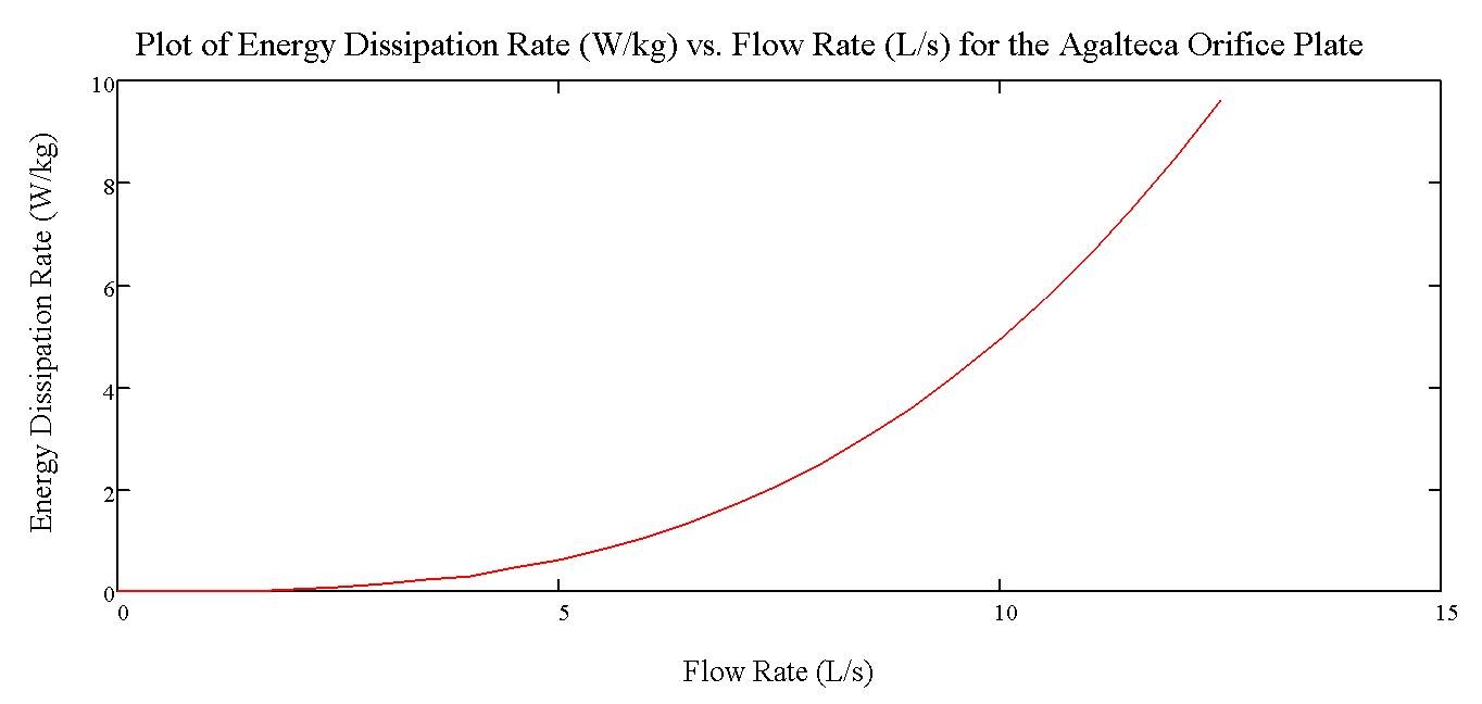
Because the flow rates through plant may vary based on the available source flow, we need to know how the energy dissipation rate will change with these changing flow rates. The following plot was generated in MathCAD to display how energy dissipation rates will change with varying flow rates through the orifice plate in place in Agalteca:
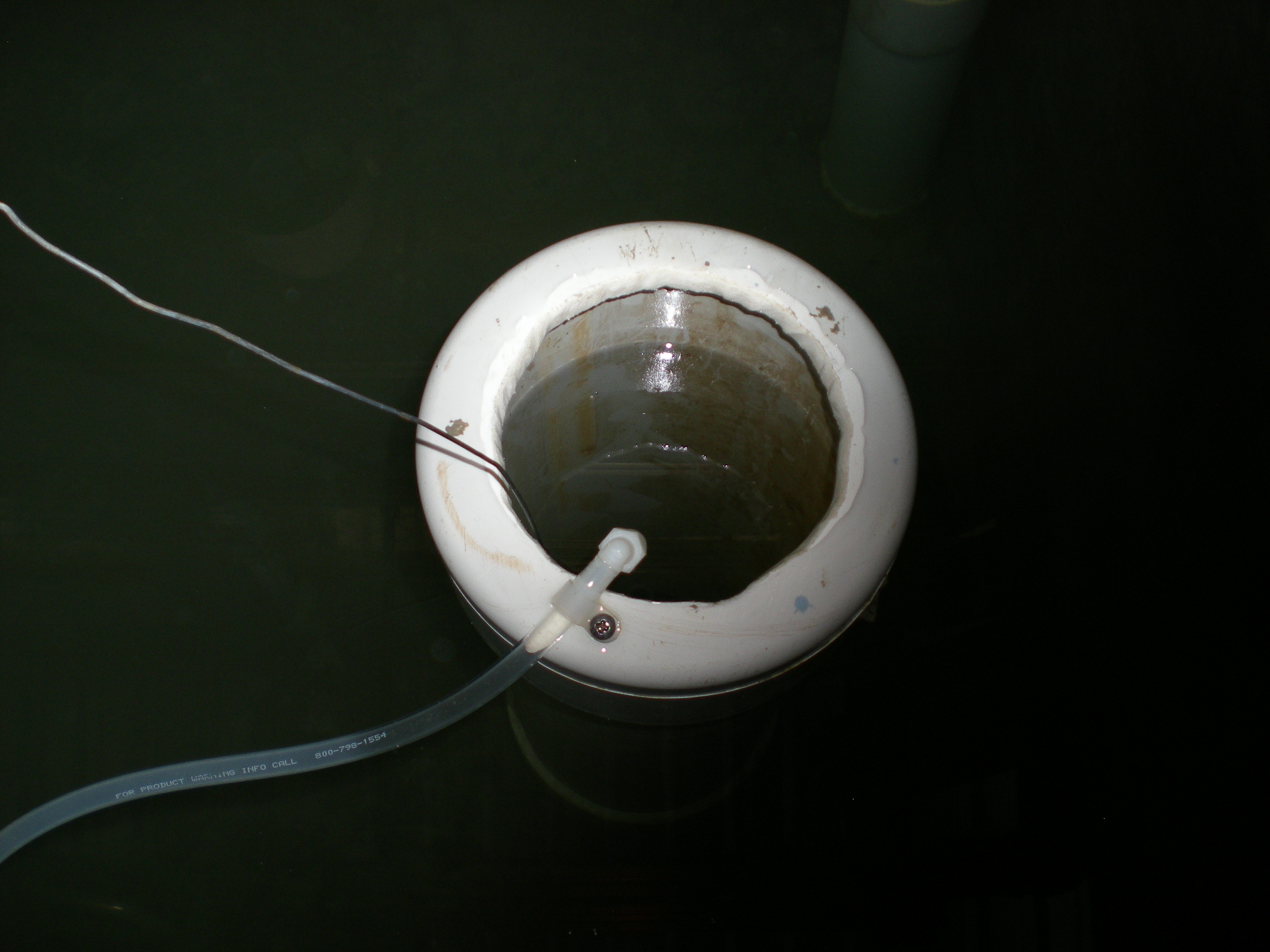
Another detail that was addressed in the Agalteca Rapid Mix Tube installation was the delivery of the dosed alum into the Rapid Mix Tube itself. To accomplish this delivery, the end of the flexible tubing running off of the doser's level arm was fitted with a small plastic elbow, then attached to the edge of the large scale mixing orifice using a small plastic clip. This allows the alum to be delivered directly into the flow of water entering the tube, improving mixing and reducing the chance that alum will escape into the entrance tank.
This delivery tube will always be submerged in the water in the entrance tank, thereby eliminating the mixture of air, water, and alum that has occurred in the previous dosing designs. This delivery modification was made in an effort to reduce the amount of air introduced to the dosing system, which will theoretically reduce any problems with floating flocs created in the flocculator, reducing plant performance. The following photo was taken at the Agalteca plant showing the new dosing delivery system. Note that the tank was drained at this point for installation of the micro mixing orifice plate, and this is why the delivery elbow is not submerged; under normal operating conditions, this elbow would be submerged and would eliminate the addition of air to dosing of alum with the raw water.