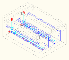
Agalteca has a population of 2,160 residents. A distribution tank is already in place, but another distribution tank is expected. Construction of an AguaClara water treatment plant started on September 30th, 2009.
Agalteca is unique in being the first plant to be designed largely using the Automated Design Tool.
There are a number of constraints which must be met when considering the dimensions and location of the entrance tank. These items are discussed below.
This is the first AguaClara design to use untapered baffles in the flocculator. The goal is to create a 6 mW/kg energy dissipation rate throughout the flocculator. There are 29 baffles in each of the first two channels to ensure that the water flows through the ports connecting channels, which are at the bottom, correctly. The last channel has 28 baffles because the inlet port is at the bottom and the inlet channel for the sedimentation tank is at the top. The baffles use polycarbonate sheets instead of cement which are easier to remove. This makes draining the system much easier.
The inlet channel was modified to have only one opening leading to the sedimentation tank instead of two. See the explanation for this under Sedimentation Tank. The concrete in the inlet channel will be rounded going into the pipe so that the transition of flow is smoother. The construction sequence for this transition will be done as follows:
before pouring the concrete for the base slab of the inlet channel, a 90 deg elbow will be coupled to the 6" pipe (substituting the chimeneys). The idea is thet the concrete follows the shape of the elbow in the bottom slab of the channel to reduce the expansion loss created by the change in direction of the flow. Please refer to the Construction sequence graphical explanation
The sedimentation tank design is significantly different from previous designs. The main problem that brought about the change is that too much sludge was settling out in the inlet manifolds at Cuatro Comunidades. There was originally a similar design for Agalteca, so it needed to be fixed. To see a list of ideas on how to fix this problem until the final design was chosen, click here. To see other potential changes that can be made if needed to correct this problem, click here.
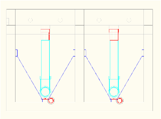
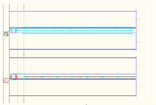
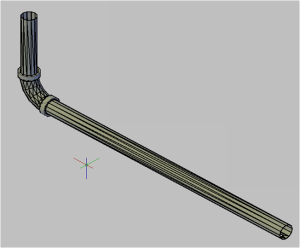
The final design involves an inlet pipe down the center of the tank instead of two inlet manifolds under the slopes. The pipe will be a 6" diameter PVC pipe. Refer to the Inlet Manifold Equations for theoretical information. This pipe will subtitute the inlet manifolds bellow the slopes which will be filled in with concrete. The slopes will remain though so that flocs are directed toward the sludge drain if they settle.
Ideally, a floc blanket will be formed. In order to more likely achieve a floc blanket, the orifices in the inlet manifold pipe will point downward, to re-elevate settled sludge along the sludge drain cover. If the floc blanket fails, the pipe can be rotated 180 degrees.
One issue that has yet to be resolved is how to distribute the flow of water evenly throughout this pipe. This includes potentially tapering the pipe and determining the size and spacing of the orifices and their positioning in relation to the sludge drain orifices. With this design, we will have more flow through the last ports of the inlet manifold pipe as the presure recovery is higher than the major headloss through the manifold. Refer to Inlet Manifold Equations.
In order to purge the floc blanket to keep the desired concentration of flocs in it, we are designing a Floc Hopper whose objective is to trap flocs and concentrate them so that when we purge, not much water is wasted. The postitioning of the floc hopper to accomplish this is yet to be determined.
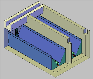
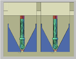
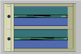
An inlet manifold is used to transport the flocs from the inlet channel to the sedimentation tank taking into account two constraints. Floc breakup and Floc sedimentation.
Floc breakup occurs when the energy dissipation is very high. From initial tests done by the AguaClara team, the maximum energy dissipation rate to prevent floc break up was 6 mW/kg. Previous plants (i.e. Cuatro Comunidades), where designed with this constraint and showed heavy sedimentation. Velocity in the manifolds was very low and particles settled here. According to the Ten State Standards, the minimum velocity of water inside a pipe should be 0.15 m/s to prevent sedimentation.
The objective of the new design was to prevent particle settling inside the manifold without increasing the energy dissipation rate to prevent floc breakup. For the final design a pipe manifold was used.
Design parameters of the manifold, results of energy dissipation rate and velocity inside the manifold are shown in the following tables.
Number of ports |
15cm |
|---|---|
Spacing between ports |
20cm |
Port Diameter |
4cm |
Maximun Energy Dissipation Rate (mW/kg) |
7.089 |
|---|---|
Velocity inside Manifol (m/s) |
0.173 |
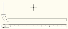
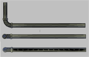
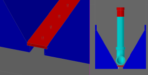
The main innovation on the sludge drain is its cover. Initially the cover served also as a support for the slope, but now, as the slopes are built by a solid piece of concrete, this is not necesary any more.
One of the advantages of the new design is that it is much easier to clean, as the only removable parts will be the 6 inch PVC inlet manifold and the drain cover which was designed in sections to make it easy to remove. Also, the fact that the flocs will settle inside the sedimentation tank, which has a sludge drain specifically designed to purge all the sludge, will imply that after emptying the tanks the remaining sludge in the bottom of the sedimentation tank will be very little to none.
The idea of designing the sludge drain cover with small orifices is to create an even vacum along the entire length of the sedimentation tank to reduce dead spaces where sludge could be accumulated.
AutoCAD drawing Click to download