*** This version of Confluence is for testing only and contains a copy of content from June 29th 2026. No changes will be preserved. ***

| Name | Size | Creator | Creation Date | Labels | Comment | |||
|---|---|---|---|---|---|---|---|---|
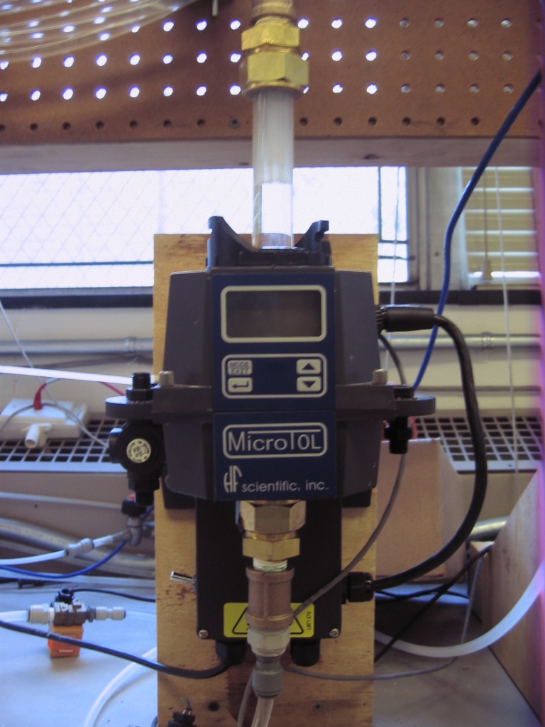
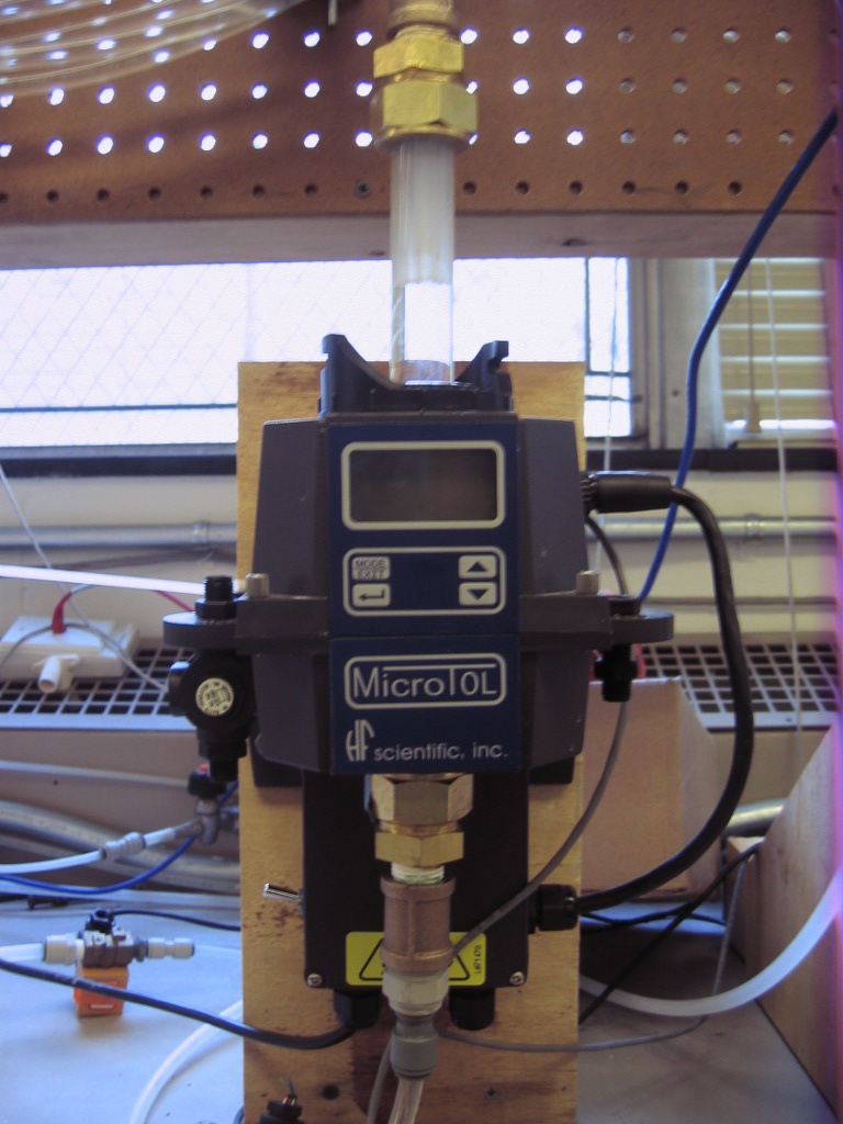
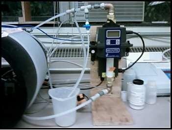
| File straight inlet.JPG | 196 kB | user-ec56f | Apr 18, 2008 16:47 |
|
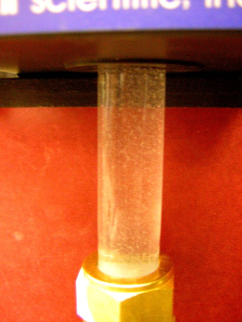
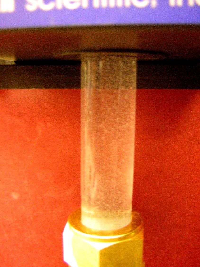
Tube Floc - Settling column with Straight inlet | |||
| Version 1 (current) | 196 kB | user-ec56f | Apr 18, 2008 16:47 | Tube Floc - Settling column with Straight inlet | ||||
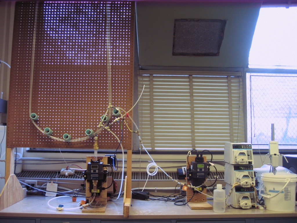
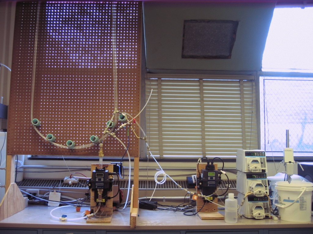
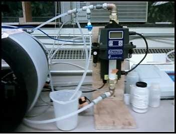
| File new setup.JPG | 306 kB | user-ec56f | Apr 18, 2008 16:46 |
|
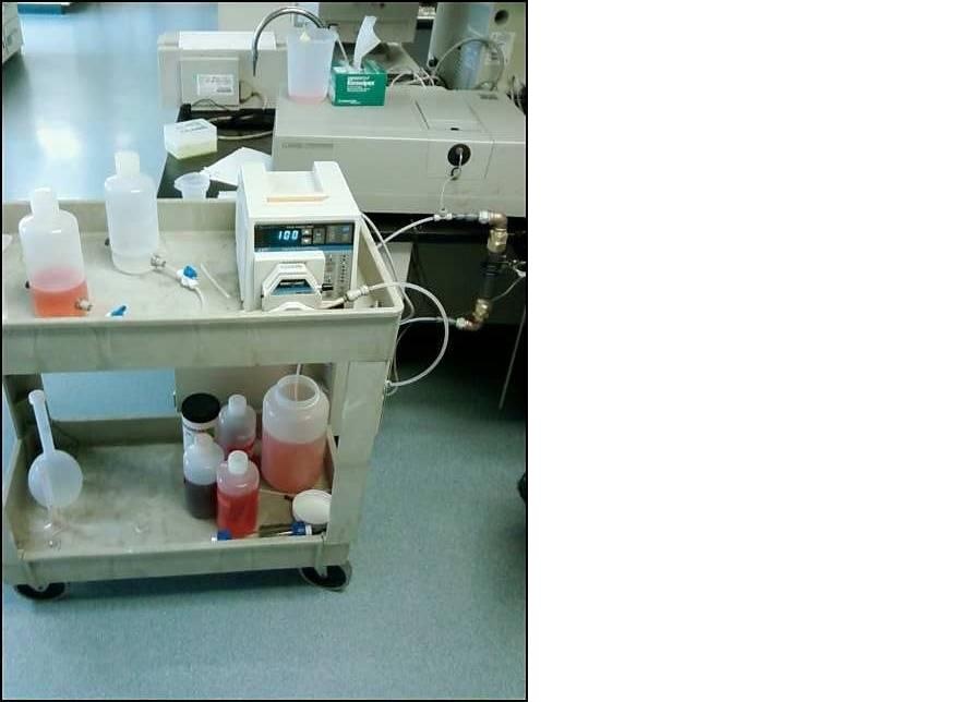
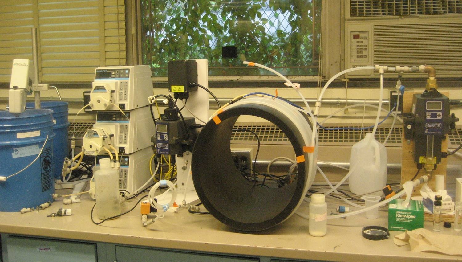
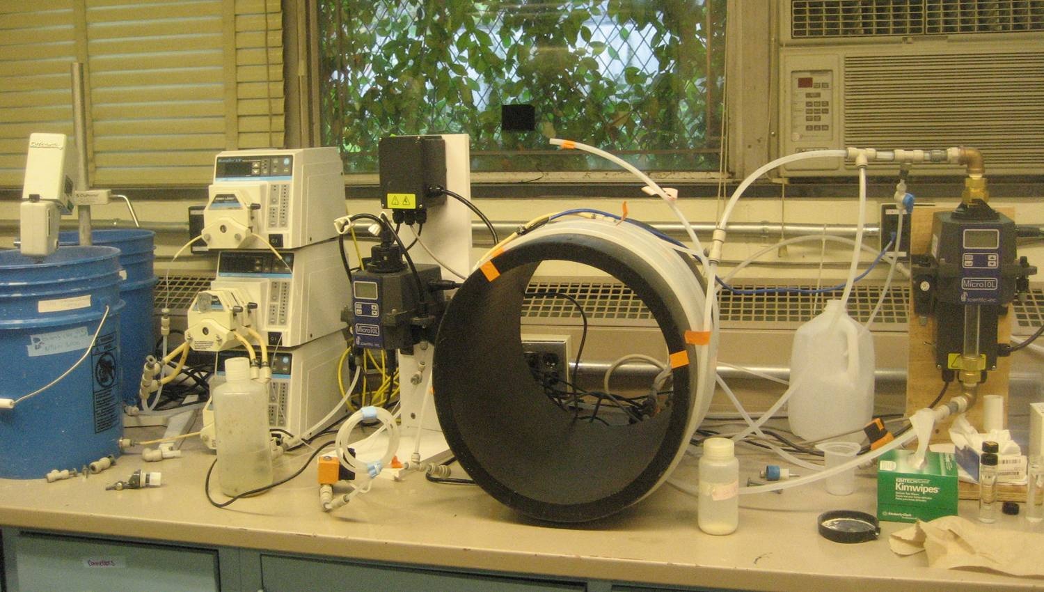
Tube Floc - New Board Setup | |||
| Version 1 (current) | 306 kB | user-ec56f | Apr 18, 2008 16:46 | Tube Floc - New Board Setup | ||||
| JPEG File Tube Floc Setup Schematic.jpg | 122 kB | user-ec56f | Feb 27, 2008 21:41 |
|
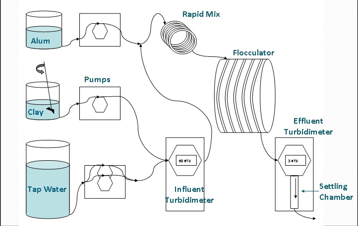
Tube Floc - Setup Schematic | |||
| Version 1 (current) | 122 kB | user-ec56f | Feb 27, 2008 21:41 | Tube Floc - Setup Schematic | ||||
| JPEG File Dye Test setup.jpg | 45 kB | user-ec56f | Feb 14, 2008 12:22 |
|
Tube Floc - Dye Test Setup | |||
| Version 1 (current) | 45 kB | user-ec56f | Feb 14, 2008 12:22 | Tube Floc - Dye Test Setup | ||||
| JPEG File Heat test setup.jpg | 19 kB | user-ec56f | Feb 14, 2008 12:19 |
|
Tube Floc - Heat Test setup | |||
| Version 1 (current) | 19 kB | user-ec56f | Feb 14, 2008 12:19 | Tube Floc - Heat Test setup | ||||
| JPEG File Tube Settler.jpg | 46 kB | user-27d2e | Feb 05, 2008 13:52 |
|
Tube Floc- Laboratory settling column | |||
| Version 1 (current) | 46 kB | user-27d2e | Feb 05, 2008 13:52 | Tube Floc- Laboratory settling column | ||||
| JPEG File Settling.jpg | 123 kB | user-27d2e | Feb 05, 2008 13:52 |
|
Tube Floc- Visualizing floc settling | |||
| Version 1 (current) | 123 kB | user-27d2e | Feb 05, 2008 13:52 | Tube Floc- Visualizing floc settling | ||||
| JPEG File Floc Setup.jpg | 186 kB | user-27d2e | Feb 05, 2008 13:51 |
|
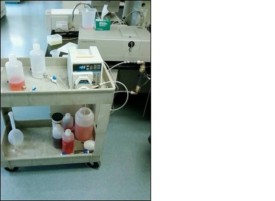
Tube Floc- Lab setup | |||
| Version 1 (current) | 186 kB | user-27d2e | Feb 05, 2008 13:51 | Tube Floc- Lab setup | ||||
| Microsoft Powerpoint 97 Slideshow Schematic.ppt | 31 kB | user-27d2e | Feb 05, 2008 13:49 |
|
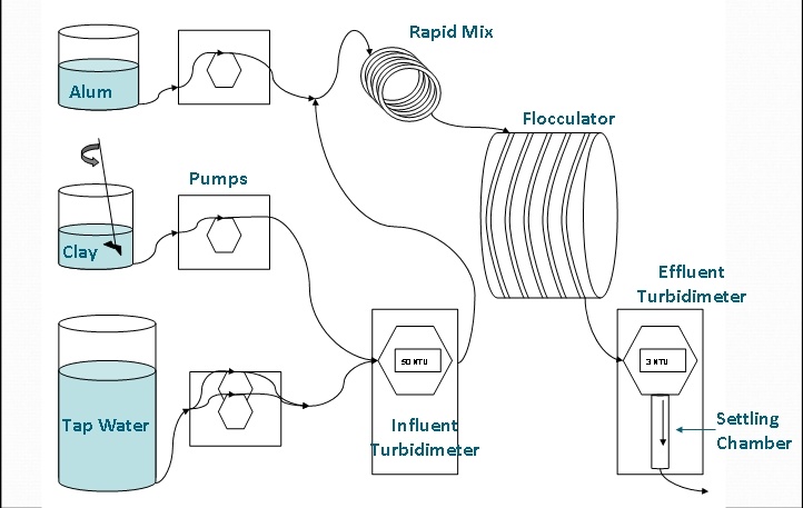
Tube Floc- Schematic | |||
| Version 1 (current) | 31 kB | user-27d2e | Feb 05, 2008 13:49 | Tube Floc- Schematic | ||||
| JPEG File image003.jpg | 10 kB | user-dd1ec | Feb 04, 2008 02:17 |
|
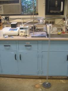
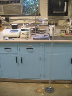
FCM- The column experimental set up for determining the relationship between flow rate and headloss (Fall 2007). | |||
| Version 1 (current) | 10 kB | user-dd1ec | Feb 04, 2008 02:17 | FCM- The column experimental set up for determining the relationship between flow rate and headloss (Fall 2007). | ||||
| JPEG File image002.jpg | 6 kB | user-dd1ec | Feb 04, 2008 02:16 |
|
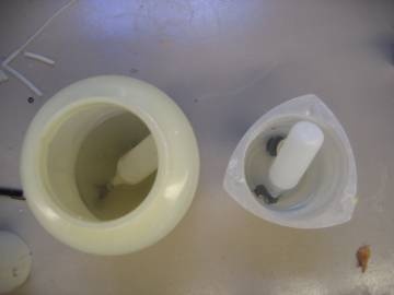
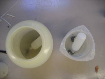
FCM- Top-down view of the float valves in chlorine (left) and alum solutions (right) for the corrosion testing (Fall 2007). | |||
| Version 1 (current) | 6 kB | user-dd1ec | Feb 04, 2008 02:16 | FCM- Top-down view of the float valves in chlorine (left) and alum solutions (right) for the corrosion testing (Fall 2007). | ||||
| JPEG File image001.jpg | 5 kB | user-dd1ec | Feb 04, 2008 02:16 |
|
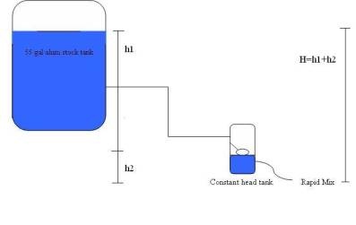
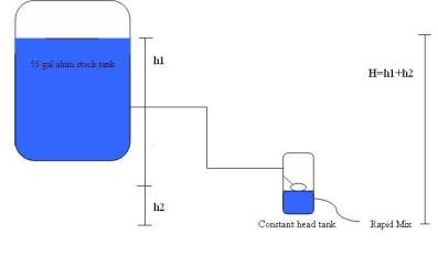
FCM- Overview of the alum dosing system where H equals the vertical distance between the alum level in the 55 gal stock tank and the effluent location, where alum enters the rapid mix. | |||
| Version 1 (current) | 5 kB | user-dd1ec | Feb 04, 2008 02:16 | FCM- Overview of the alum dosing system where H equals the vertical distance between the alum level in the 55 gal stock tank and the effluent location, where alum enters the rapid mix. |
DEVELOPER LICENSE - This Confluence site is for non-production use only.