*** This version of Confluence is for testing only and contains a copy of content from June 29th 2026. No changes will be preserved. ***

| Wiki Markup |
|---|
h1. CFD Sedimentation Tank Simulation h2. Overview {float:right|border=2px solid black|width=200px} [!sedimentation tank manifold design.jpg|width=200px!|CFD Sedimentation Tank Simulation] {float} To model the flow (experimentally/computationally) distribution in the bottomexisting design of a sedimentation tank, and to devise an optimal design for creating uniform flow. CFD Sedimentation Tank Simulation [goals|CFD STS Goals] and [meeting minutes|CFD STS Meeting Minutes]. h2. Problem Specification h4. Existing Design {float:right|border=2px solid black|width=200px} [!existing design.jpg|width=200px.jpg|width=50,height=100!|CFD Sedimentation Tank Simulation] {float} |
In
...
the
...
latest
...
design
...
of
...
sedimentation
...
tank,
...
we
...
use
...
a
...
V-shaped
...
tank
...
bottom
...
to
...
collect
...
and
...
drain
...
the
...
settled
...
flocs,
...
with
...
influent
...
pipes
...
installed
...
along
...
the
...
slopes.
...
...
| Wiki Markup |
|---|
{float Challenges {float:right|border=2px solid black|width=200px} [!modifiedsedimentation tank manifold design.jpg|width=200px50,height=100!|CFD Sedimentation Tank Simulation] {float} |
In
...
a
...
newly
...
proposed
...
design,
...
we
...
will
...
make
...
better
...
use
...
of
...
the
...
space
...
under
...
the
...
surface
...
of
...
V-shaped
...
bottom,
...
replacing
...
the
...
concrete
...
with
...
void
...
space
...
for
...
influent
...
water,
...
and
...
create
...
water
...
inlet
...
at
...
the
...
bottom
...
of
...
the
...
slopes.
...
In
...
this
...
new
...
design,
...
we
...
use
...
less
...
concrete
...
and
...
less
...
pipes
...
to
...
bring
...
down
...
the
...
cost,
...
and
...
avoid
...
the
...
instability of
...
upward
...
flow
...
caused
...
by
...
multiple
...
pipes
...
at
...
the
...
bottom.
...
The
...
major
...
challenge
...
in
...
this
...
new
...
design
...
is
...
how
...
to
...
configure
...
geometry
...
of
...
the
...
water
...
inlet
...
at
...
the
...
bottom
...
of
...
the
...
slopes
...
to
...
create
...
flows
...
as
...
uniform
...
as
...
possible.
...
Intuitively,
...
there
...
are
...
three
...
basic
...
situations
...
of
...
the
...
water
...
inlets.
...
...
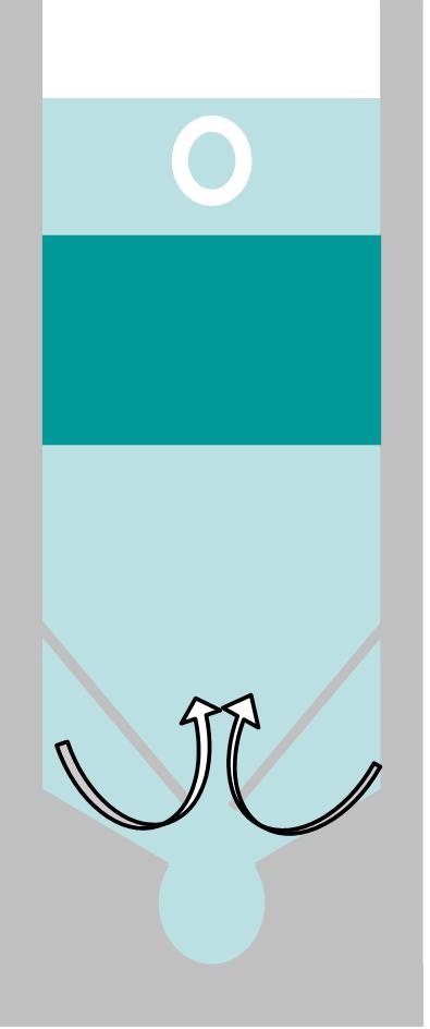
Openings for water inlets on bothsides. Water flows from both sides,collide with each other and rise in the middle.
...
...
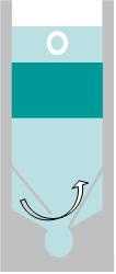
Opening for water inlets on one side. Water flows from one side, collide and rise along with the slope on the other side.
...
...
Opening on neither side. No flow from either side.

...
...
The flow field in the specified problem is completely complex 3D flow. However, in order to make the problem more doable we will start from simulating 2D cross-sections as analyzed above.