 Sign-up for free online course on ANSYS simulations!
| Include Page | ||||
|---|---|---|---|---|
|
...
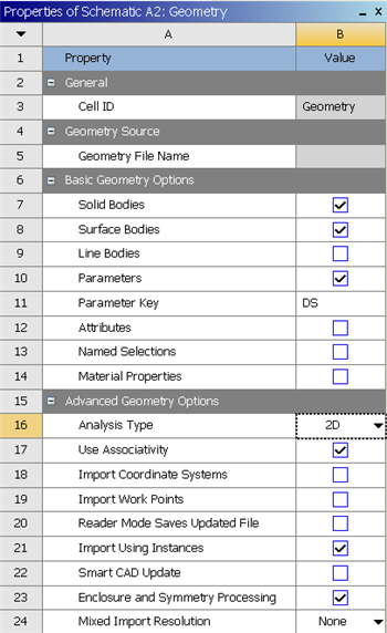
Our geometry is 2D. At Workbench, in the Beam cell, right click on Geometry, and select Properties. You will see the properties menu on the right of the Workbench window. Under Advance Geometry Options, change the Analysis Type to 2D.
In the Project Schematic, double left click on Geometry to start preparing the geometry.
At this point, a new window, ANSYS Design Modeler will be opened. You will be asked to select desired length unit. Use the default meterunit and click OK.
Strategy for Geometry Creation
...
Start by creating a sketch on the XYPlane. Under Tree Outline, select XYPlane, then click on Sketching next to Modeling tab. This will bring up the Sketching Toolboxes.
Note: In sketching mode, there is Undo features that you can use if you make any mistake. 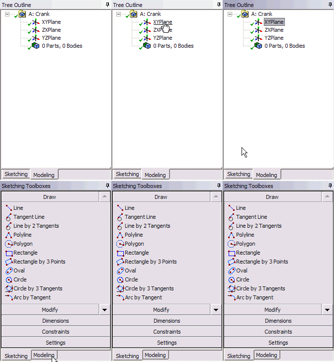
| newwindow | ||||
|---|---|---|---|---|
| ||||
https://confluence.cornell.edu/download/attachments/112041403/Select+Sketching+Toolboxes.gif |
On the right, there is a Graphic window. At the lower right hand corner of the Graphic window, click on the +Z axis to have a normal look of the XY Plane. 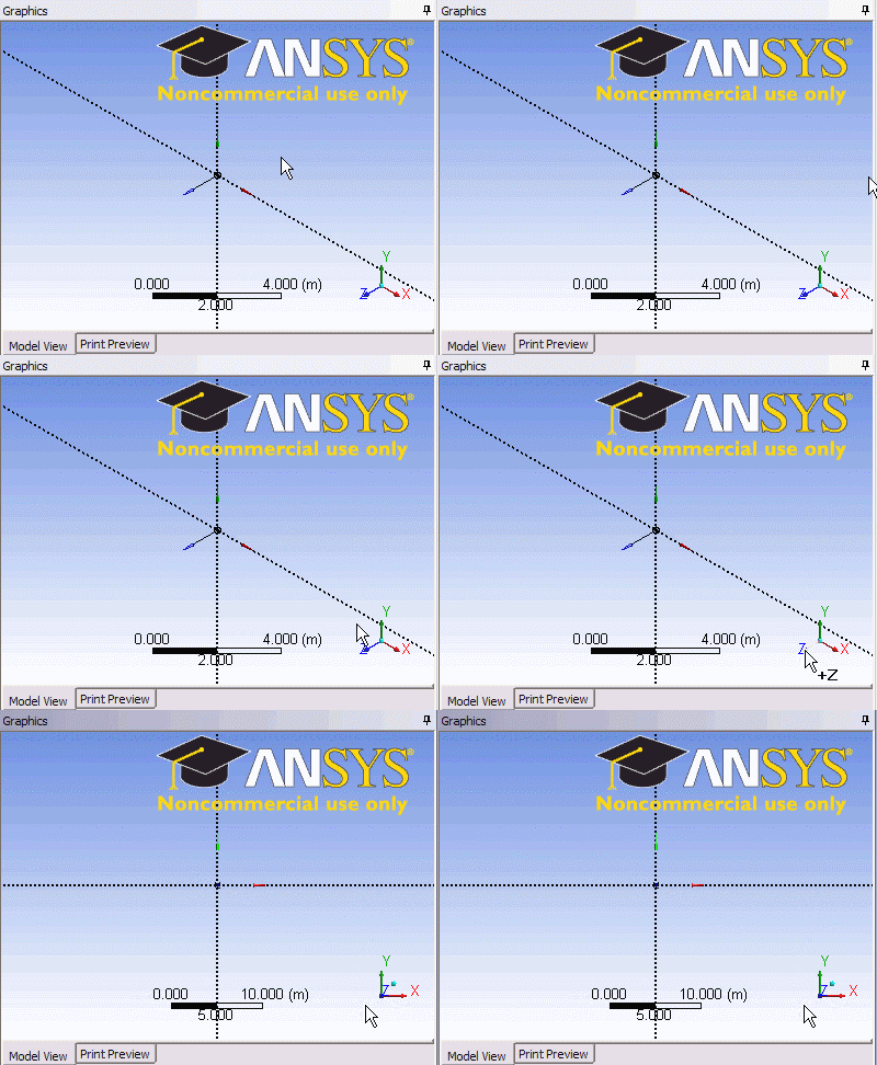
| newwindow | ||||
|---|---|---|---|---|
| ||||
https://confluence.cornell.edu/download/attachments/112041403/Select+Normal+View.gif |
In the Sketching Toolboxes, select Rectangle. In the Graphicswindow, create a rough Rectangle from starting from the origin in the positive XY direction (Make sure that you see a letter P at the origin before you start dragging the rectangle. The letter P at the origin means the geometry is constrained at the origin.)
...
We would like to split the top and bottom with three edges. Click Modify tab and select Split. Roughly select four points on the top and bottom of the rectangle.
...
Dimensions and Constraints
Under Sketching Toolboxes, select Dimensions tab, use the default dimensioning tools. Dimension the geometry as shown:
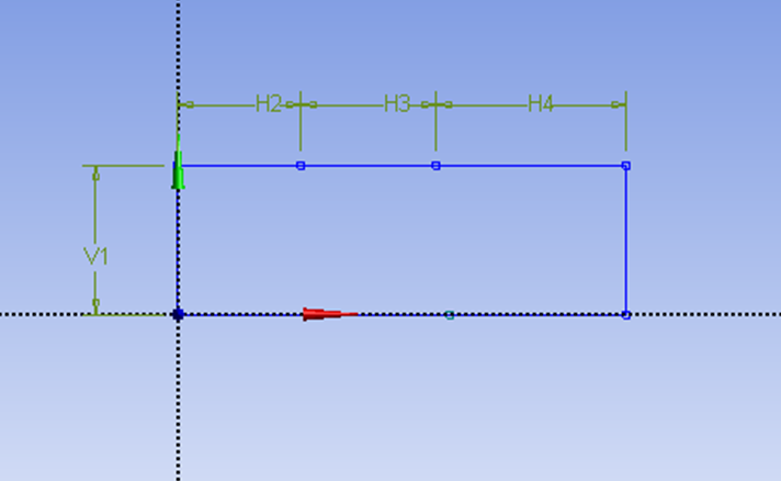
Now we need to constraint the lower rectangle with the top of the rectangle which has been properly dimensioned. Click Constraints tab, select Equal Length. Click the appropriate top and bottom edge and set them to be of equal length.
Under Details View on the lower left corner, input the value for dimension appropriately.
V1: 0.05 m
H2: 0.1 m
H3: 0.2 m
H4: 0.1 m
...
This will create a new surface SurfaceSK1. Under Details View, select Sketch1 as Base Objects and click Apply. Finally click Generate  to generate the surface. This is what you should see under your Tree Outline.
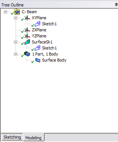
You can close the Design Modeler and go back to Workbench (Don't worry, it will auto save).