*** This version of Confluence is for testing only and contains a copy of content from June 29th 2026. No changes will be preserved. ***

...
The goal of our research is to evaluate the feasibility of a siphon-aided backwash design to be used for a sand or mixed-media down-flow filter. The benefits of siphon-aided backwash are:
1) The height of the clear-well does not need to be equal to the the head pressure required to attain 30%-50% expansion.
2) The siphon tube is designed to fill up when the filters have reached a terminal headloss (a set point we determine). Thus, they only backwash when they are dirty.
3) Since the headloss energy is used to prime the siphon, and eventually trigger backwash, fewer valves are required which reduces cost and labor.
filter bed can be right next to the clear-well, connected via an open pipe without a valve. Flow of water into and out of the clear-well will be controlled by valves on the influent and backwash manifolds.
3) Using 55 gallon HDPE barrels, we will create a system of parallel filters surrounding a shared clear-well. By backwashing the filters out of phase, we will reduce the demand for a large clear-well. Additionally, the downflow filters will be filling the clear-well while the other filters being backwashed draw from it. This allows faster clear-well recharge rates and shortens the time between consecutive backwash cycles.
An example of a patented siphon-aided backwash design (Automatic Valveless Gravity Filter)Here is a useful animation
The filter bed rests inside an air-tight container. The influent enters through a port above the sand bed. The siphon is also connected through a separate port, connected to the container, above the sand bed. The clean water exits the container below the sand bed, which leads to clear-well storage.
...
In backwash mode: The siphon is "primed" by the headloss generated in the clogging filter, which causes the raw water to flow up the siphon tube. Eventually the water begins to flow over the bend of the siphon and as it fills the tube, a negative pressure gradient is established, diverting all flow out the siphon.
Water from clear-well flows in reverse>sand bed (from bottom)>siphon>waste
We have modeled a siphon filter system for a plant similar in size to Aguateca. The design is based on a 55 gallon drum, a commodity known to be accessible and cheap in Honduras. We wished to experiment with a well screen filter below the sand in place gravel, which is more commonly used. A basic schematic of the siphon filter system is shown below:
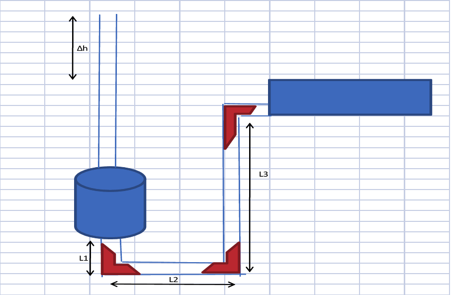
We modeled the filter in regular down-flow mode to size the system and determine the necessary pressure drops. By calculating the head loss across the filter system, we will determine the necessary height difference from the sedimentation tank to the filter. We have generated a model in Mathcad using the relations below:
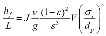
The sand bed pressure drop was modeled with the Carman Kozeny equation:
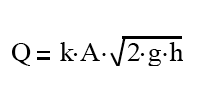
The pressure drop across the well screen was modeled with the orifice equation (for summation of holes):
The head loss across the piping and fittings was calculated using parameters from Morton M. Denn's Process Fluid Mechanics (page 93):
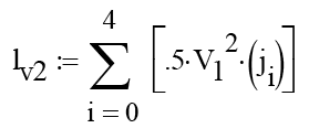
Viscous Losses due to fittings 2/s^2
Where is the "velocity heads lost" Coefficent, Kf
Concentric well screen filter design
Offset filter bed design
55 Gallon Barrel Filters with Shared Clear Well
Single 55 gallon barrel filter schematic
Height required to attain backwash velocity (with headloss calculations)
1)Sand level monitoring
-Plexi-glass viewing strip on barrel side
2)Pressure across filters-when do the filters need to be back-washed?
-piezometer
3)Backwash Velocity- achieve bed expansion without losing sand
-Gate valve on siphon tube
4)Flow distribution during backwash-avoiding shocks to the system
5)Bypass -for seasons when filtration is unnecessary
1)8 parallel filters: where 7 down-flow filters backwash 1 filter
-Problem: not flexible for variable plant flow rates
-If multiple filters are dirty, can not achieve desired backwash velocity
2)Clear well might be necessary
-Constant backwash velocity
-If multiple filters are dirty, filters can still be back-washed
3)Backwash from sedimentation tank
-Is using raw water for backwash okay?
-At end of backwash ~6 inches of dirty water is retained in bed, so the first distribution of water after backwash will have high turbidity
Bench top model:
-Test how changing the height difference (between the water level in the clear well to the bottom of the siphon) influences backwash velocities.
-Fine-tune the backwash velocity using a gate valve on the siphon tubeAfter initial calculations with typical parameters from well screen manufacturers, we calculated a head loss on the order of 8 meters across the screen. This amount of head is too large to proceed, therefore we have abandoned the use of a well screen and will use the traditional solution, gravel. Our next step will be to model the siphon back wash mechanism.