*** This version of Confluence is for testing only and contains a copy of content from June 29th 2026. No changes will be preserved. ***

...
Primary Reflector Parabola (Side View)
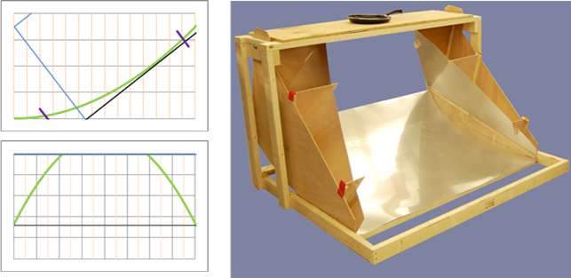
Secondary Reflector Parabola (Front View)
Figure 2 - Combining simple geometry with wide area using the secondary-reflector concept
...
The team decided that a useful cooker should be operable for a minimum of 2 hours per day on the shortest day of the year. Tim Bond gave us an approximate Nicaragua latitude, from which we calculated that solar elevations ranging from 52o to 90oshould provide just under 2 hours of cooking on the shortest day of the year and 6 - 8 hours during the summer. The section titled Solar Elevation Calculations for Concentrated Cooker, found on the following page, provides complete calculations. Having determined the desired area and range of movement for the reflector assembly, the team was equipped to seek appropriate dimensions and focal lengths for the primary and secondary reflectors. To this end, the team created models of the reflectors in an excel spreadsheet to allow us to experiment with various parameters and observe the effects. This excel file, named Concentrating_solar_cooker_VISUALIZER.xlsis on the CD and should also be available on the website.
...
Knowing this, we knew that the secondary reflectors needed at least 1.1m of "useful width" in order to provide the power necessary. The "secondary reflector" tab in the excel modeler graphs a parabolic shape relative to the tabletop and to the lower bound of how far the reflectors may extend. The allowable height of the secondary reflectors was found by subtracting the tallest point of the primary reflector from the total tabletop height. With this number in place, the user is allowed to experiment with the "intersect width" (which is a function of focal length). The modeler then calculates the resultant width of the X-dimension, given the height constraint. It also gives a corrected, "true width" to account for energy "wasted" from sunlight that lands on the flat space between the edge of the cooking hole and the beginning of the secondary reflector. From this model, we were able to determine that an intersect width of 0.75m gave a total width of 1.613m and a "true width" of 1.117m. Thus, we were able to achieve the collector surface area required and could feel confident about anticipated performance as we began construction. The section entitled Concentrated Cooker Technical Specifications, found on the following page, provides a summary of the concentrating cooker's dimensions and technical specifications.
...
The solar elevation angle is the angle formed between the sun and the horizon. Thus, the solar elevation is 0o at sunrise or sunset and 90owhen the sun is directly overhead such that objects do not cast a shadow. It is often denoted as qΘS and can be calculated using Equation 1:

Where: qS = solar elevation angle
h = hour angle, in the local sidereal time
d = current sun declination
F = local latitude
The hour angle h is an expression of solar time for a given point on earth. It is the angle through which the earth must turn in order to bring the meridian of that point directly under the sun. Thus, the hour angle is 0o at solar noon and changes by 15owith each hour of the day. The hour angle is considered negative in the AM and positive in the PM.
Wiki Markup
The sun declination d is the angle between the sun's rays and the plane of the earth's equator; it can be found using Equation 3:
(3)
Where: N = day of the year (number of days spent since Jan 1)
Thus: 
Thus, the solar elevation at any given time and place can be calculated based on 3 inputs: local latitude, current hour, and current date.
In designing the concentrating cooker, our team sought to ensure that the cooker would be useful for a minimum of 2 hours per day in Nicaragua. The solar angle equations given above allowed us to calculate the minimum solar angle the cooker must therefore accept in order to meet this boundary condition. The local latitude in Nicaragua is about 13o N, and we use an hour angle of ±15o in order to bound one hour before and after solar noon. Since the smallest number of useful cooking hours occurs on the shortest day of the year, we calculate solar declination d using N = 355 (corresponding to the winter solstice, December 21):
0.7739
à) = 50o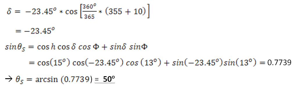
Reflector Assembly | Tabletop | Performance |
- Total width: 1.613 m | - Cooking hole: 10" across | - Minimum solar elevation: 52° |
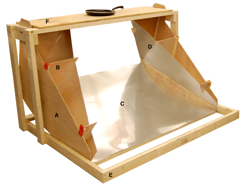
A - Side Panel for Secondary Reflector
...
The construction of the parabolic cooker went fairly smoothly due to the careful and lengthy design process. The team began construction on the cooker Nov. 28, 2009 and attached the table top Dec. 8, 2009. Work began on the secondary reflectors first, since they required the most construction time. Side panels for the secondary reflector were cut from ¼" plywood. Next, the fins were cut from ¼" plywood. These fins would attach the sheet metal to the side panels and form the parabolic shape of the secondary reflectors. The fins were designed such that the sheet metal would slide into slots cut into the fins at the top, and strips of ¼" plywood were glued in a straight line along the base of the side panel to hold the bottom of the sheet metal. ½" plywood strips and wood glue were used to attach the fins to the side panels. Pieces of ¼" plywood were glued to the bottom curve of the side panels to fold the parabolic shape of the primary reflector. See figure 1 below for further details.
The Figure 1 - Construction of Secondary Reflectors The frame of the cooker was built next. This was fairly simple as it was constructed entirely from 2X4 boards, and held together by 2" wood screws. The entire reflector assembly was attached from the side panels of the secondary reflector to the frame by two bolts. The three figures below provide additional detail.
...
Once the secondary reflectors were attached to the frame, the primary reflector was slid into place, and 4 struts were attached underneath the sheet metal reflector, connecting the secondary reflectors together. This completed the reflector assembly, which is able to effectively "swing" from the frame to compensate for the varying solar angles. The struts were attached to the side panels of the secondary reflector using metal L-brackets and 1" wood screws.
The basic cook top was made from ½" plywood. A 10" diameter hole is cut in the middle. A 10" hole was the design specification the team had calculated given the parabolic shapes of the reflectors. The cook top and hole have not yet been insulated to prevent the cook top from burning. See figure 5 below for further detail.
Figure 5 - Constructing the Cook Top 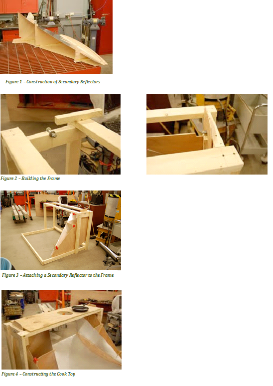
...