*** This version of Confluence is for testing only and contains a copy of content from June 29th 2026. No changes will be preserved. ***

...
A sensitivity analysis of Reynolds number was determined for the flocculation height tank height of .3 with a symmetry boundary condition on the top of the flocculation tankhas been completed. The performance of the flocculator was examined at Re=1,000 (corresponding to a velocity inlet of .01 m/s), Re=10,000 (corresponding to a velocity inlet of .1 m/s), and Re=100,000 (corresponding to a velocity inlet of 1 m/s).
...
The velocity profiles for varying Reynolds numbers are presented below. With increasing inlet velocities, the uniformity of the flow clearly decreases. This can be seen by how the ratio of the maximum velocity over the inlet velocity increases, as well by the profiles.
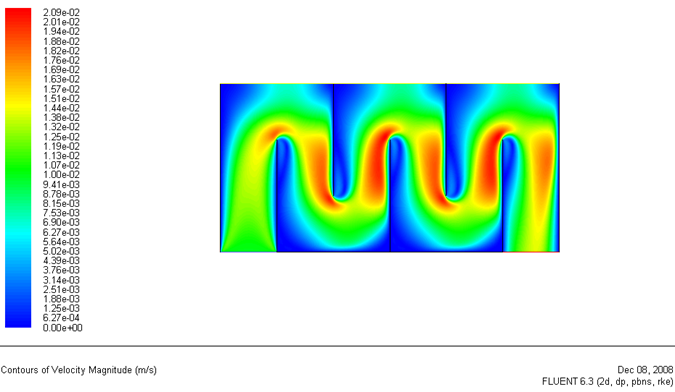
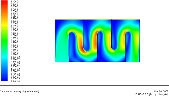
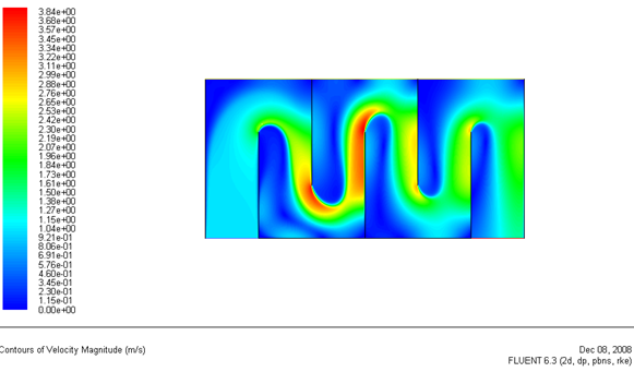
For the case when the Reynolds number is 1,000, the flow is in the laminar region, and the fluid behaves similarly across different baffles. The velocity profile, which has a maximum magnitude of only twice the inlet value, reveals that the recirculating region is smaller, and the fluid does not impinge on the baffle following it. The velocity profile of the Re=100,000 case shows that the fluid does not have a high enough viscosity to turn around the bends efficiently. After each turn the fluid impinges upon the baffle following it. The flow over the first baffle channels the fluid creating an extremely high velocity region at the edge of the second baffle. Following this baffle there is an extremely high region of velocity correspond to how a lot of fluid is forced against the edge of the third baffle.
...
The normalized energy dissipation for varying Reynolds Numbers is presented below. With increasing Reynolds numbers, the energy dissipation profile reveals a greater amount of energy dissipation in areas where the fluid impinges on the following baffle.
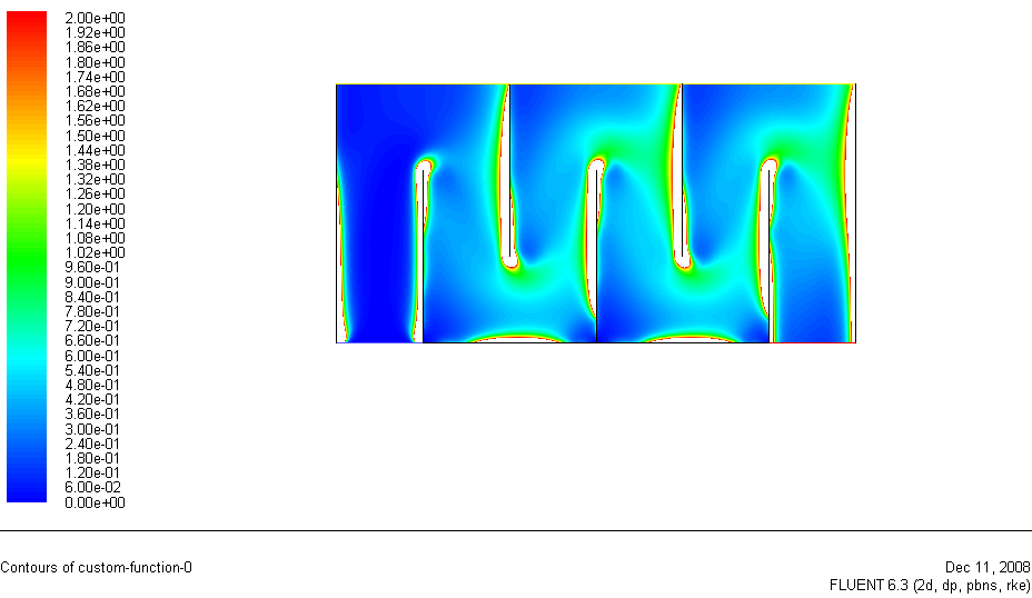
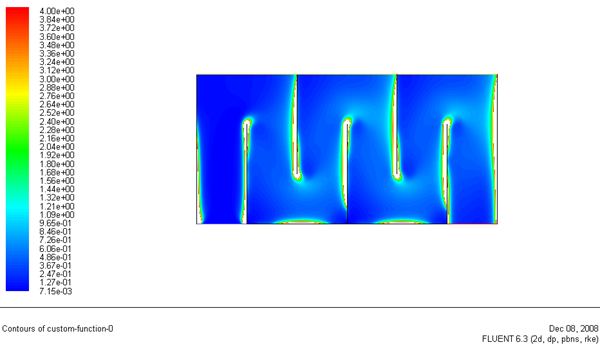
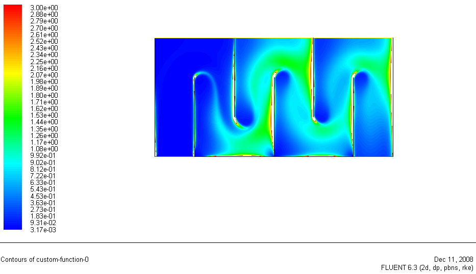
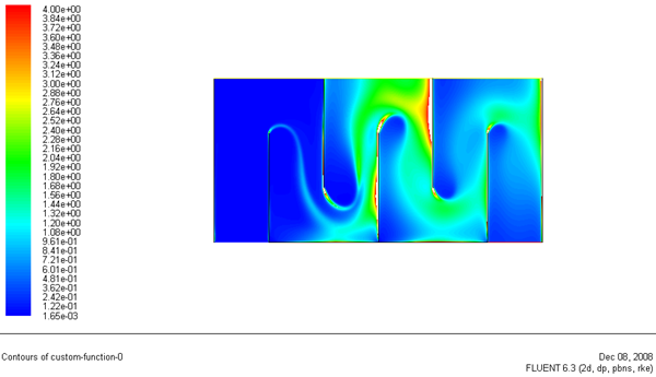
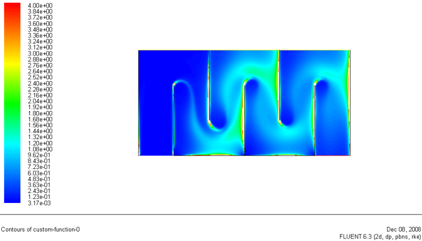
The normalized energy dissipation profile in Figure 4 reveals that the fluid only dissipates energy due to the no slip conditions on the wall. Otherwise, the energy dissipation is quite boring, and there is little energy dissipation induced in the main portion of the flow of the fluid, even after the baffles. Comparing the normalized epsilon values which are scaled to the same value, the higher Reynolds number flow makes more efficient use of the flocculator.
...