*** This version of Confluence is for testing only and contains a copy of content from June 29th 2026. No changes will be preserved. ***

...
...
...
...
...
...
This
...
flocculator
...
program
...
determines
...
the
...
size,
...
number,
...
and
...
spacing
...
of
...
the
...
flocculator
...
channels
...
and
...
baffles,
...
based
...
on
...
the
...
results
...
of
...
the
...
Computational
...
Fluid
...
Dynamics
...
(CFD)
...
team
...
and
...
the
...
specification
...
of
...
horizontal
...
flow.
...
Horizontal
...
flow
...
is
...
used
...
for
...
very
...
high
...
flow
...
rates
...
to
...
avoid
...
building
...
the
...
plants
...
even
...
taller,
...
instead
...
making
...
them
...
wider.
...
Horizontal
...
flocculators
...
are
...
also
...
easier
...
to
...
drain
...
than
...
vertical
...
flocculators
...
made
...
of
...
cement
...
baffles
...
because
...
individual
...
drains
...
are
...
not
...
needed
...
for
...
every
...
lower
...
baffle
...
as
...
they
...
are
...
in
...
the
...
vertical
...
flocculator.
...
The
...
tank
...
is
...
designed
...
given
...
an
...
optimal
...
energy
...
dissipation
...
rate
...
to
...
maximize
...
the
...
opportunity
...
for
...
flocs
...
to
...
form
...
and
...
to
...
produce
...
flocs
...
that
...
are
...
small
...
enough
...
that
...
they
...
can
...
be
...
transported
...
to
...
the
...
sedimentation
...
tank
...
without
...
breaking.
...
The
...
program
...
also
...
outputs
...
arrays
...
of
...
the
...
location
...
of
...
each
...
baffle
...
in
...
the
...
tank;
...
these
...
arrays
...
are
...
used
...
by
...
the
...
AutoCAD
...
scripts
...
to
...
draw
...
the
...
baffles
...
in
...
place
...
in
...
the
...
flocculator.
...
The
...
programs
...
used
...
are
...
Flocculator
...
3
...
(the
...
design
...
program)
...
and
...
floctank
...
(
...
...
...
...
).
...
In
...
the
...
scheme
...
of
...
the
...
whole
...
plant,
...
the
...
flocculation
...
tank
...
is
...
drawn
...
after
...
the
...
sedimentation
...
tank
...
(so
...
many
...
of
...
our
...
variables
...
are
...
constrained
...
by
...
an
...
already-drawn
...
sedimentation
...
tank).
...
The
...
design
...
program
...
from
...
horizontal
...
flow
...
is
...
integrated
...
into
...
the
...
same
...
program
...
used
...
to
...
design
...
vertical
...
flow
...
flocculators
...
and
...
an
...
...
is
...
used
...
to
...
select
...
between
...
the
...
two
...
designs.
Generic | Vertical | Horizontal |
Ρ | W | H |
S | S | S |
J | H | W |
To create a consistent relation between vertical and horizontal flow, generic notation is used. J represents the flow travel distance between flow direction changes. The flow area, which is the cross sectional area that is perpendicular to the flow of the water, is P*S.
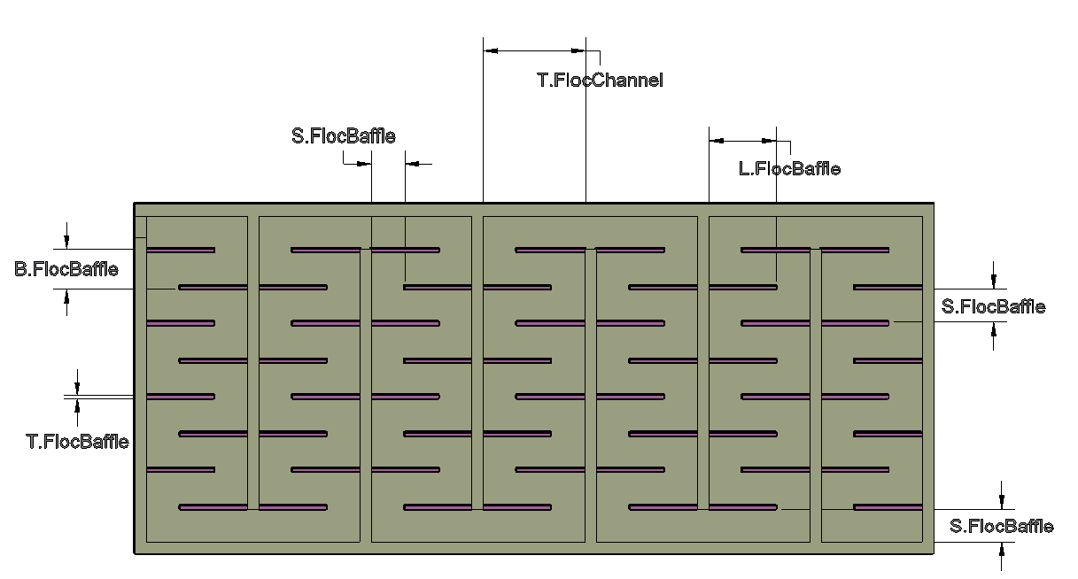
Each section outlined below corresponds to its equivalent MathCAD code, identified by the same titles.
To view the first part that informs and establishes the equations and design ideas used in the actual drawing of the tank refer to the Vertical Flow Flocculation Design Program page as these equations and ideas are the same.
The second part determines the number, spacing, energy dissipation, and collision potential of the necessary baffles.
The third part determines the width, height, size, and the other parameters needed to draw the flocculation tank with the baffles inside it. This section is heavily relied upon by the MathCAD code in floctank that draws the plant.
The last part creates and outputs the matrix of baffle positions.
The critical balance in the flocculator is between ensuring that the alum and entering water are meeting the energy dissipation (ED) and collision potential (CP) goals, and not breaking up flocs that have formed.
Calculating the number of baffle spaces that gives the target ED and CP is done with a non-iterative code (as opposed to the vertical code which is iterative sometimes). The optimal J/S value of 3 found from the CFD calculations can be used for horizontal flocculators since the flocculator can be made as wide as necessary (whereas in vertical flocculation, J was constrained by the height of the sedimentation tank), so iteration is not needed. The space between two baffles is determined using the following code:
| Latex |
|---|
| Generic | Vertical | Horizontal | | Ρ | W | H | | S | S | S | | J | H | W | To create a consistent relation between vertical and horizontal flow, generic notation is used. J represents the flow travel distance between flow direction changes. The flow area, which is the cross sectional area that is perpendicular to the flow of the water, is P*S. h2. Top View !Horizontal Top Dimensions.PNG|width=1081,height=596! h2. Flocculation Design Algorithm Each section outlined below corresponds to its equivalent MathCAD code, identified by the same titles. To view the first part that informs and establishes the equations and design ideas used in the actual drawing of the tank refer to the [Vertical Flow Flocculation Design Program] page as these equations and ideas are the same. The second part determines the number, spacing, energy dissipation, and collision potential of the necessary baffles. The third part determines the width, height, size, and the other parameters needed to draw the flocculation tank with the baffles inside it. This section is heavily relied upon by the MathCAD code in floctank that draws the plant. The last part creates and outputs the matrix of baffle positions. h2. Flocculator Functions The critical balance in the flocculator is between ensuring that the alum and entering water are meeting the energy dissipation (ED) and collision potential (CP) goals, and not breaking up flocs that have formed. Calculating the number of baffle spaces that gives the target ED and CP is done with a non-iterative code (as opposed to the vertical code which is iterative sometimes). The optimal J/S value of 3 found from the CFD calculations can be used for horizontal flocculators since the flocculator can be made as wide as necessary (whereas in vertical flocculation, J was constrained by the height of the sedimentation tank), so iteration is not needed. The space between two baffles is determined using the following code: {latex} \large $$ S = \mathop {\left( {{{\mathop Q\nolimits_{Plant} } \over {\mathop P\nolimits_{FlocChannel} }}} \right)}\nolimits^{{3 \over 4}} \mathop {\left( {{1 \over {\mathop {Pi}\nolimits_{JS} }}} \right)}\nolimits^{{1 \over 4}} \mathop {\left( {{{\mathop K\nolimits_P \mathop \alpha \nolimits_\varepsilon } \over {2ED}}} \right)}\nolimits^{{1 \over 4}} $$ {latex}} \\$$ |
The
...
number
...
of
...
spaces
...
per
...
channel
...
is
...
determined
...
by
...
a
...
non-iterative
...
code
...
also
...
since
...
the
...
length
...
of
...
the
...
channels
...
are
...
fixed
...
to
...
be
...
the
...
length
...
of
...
the
...
sedimentation
...
tank.
...
Unlike
...
in
...
vertical
...
flow
...
flocculation,
...
channels
...
will
...
always
...
have
...
an
...
odd
...
number
...
of
...
spaces
...
to
...
ensure
...
that
...
water
...
flows
...
into
...
successive
...
channels
...
and
...
eventually
...
into
...
the
...
sedimentation
...
tank.
...
See
...
Calculation
...
of
...
Flocculator
...
Geometry
...
for
...
this
...
equation.
...
...
...
...
...
The
...
depth
...
of
...
water
...
at
...
the
...
end
...
of
...
the
...
flocculation
...
tank
...
is
...
set
...
by
...
the
...
user.
...
The
...
different
...
options
...
are
...
described
...
in the algorithm that chooses between horizontal and vertical. If the floc tank is shallower than the sed tank, the floc tank is elevated so that the water levels match.
The number and spacing of floc spaces and floc baffles is calculated, as well as the Collision Potential, for the specific tank being drawn. The number of floc spaces is determined using the following function which forces the number of spaces to be an odd integer:
| Latex |
|---|
the [algorithm|Choosing Horizontal or Vertical] that chooses between horizontal and vertical. If the floc tank is shallower than the sed tank, the floc tank is elevated so that the water levels match. The number and spacing of floc spaces and floc baffles is calculated, as well as the Collision Potential, for the specific tank being drawn. The number of floc spaces is determined using the following function which forces the number of spaces to be an odd integer: {latex} \large $$ {N_{FlocSpacesF}}(L,{\rm{T}},S) = Floor({{L + {\rm{T}}} \over {S + {\rm{T}}}} + 1,2) - 1 $$ {latex} \\ When calculating the |
When calculating the spacing,
...
L
...
represents
...
the
...
length
...
of
...
the
...
sed
...
tank
...
L.Sed
...
and
...
T
...
represents
...
the
...
thickness
...
of
...
a
...
baffle
...
T.FlocBaffle
...
.
...
The
...
minimum
...
baffle
...
spacing
...
is
...
45
...
cm,
...
which
...
is
...
the
...
width
...
that
...
a
...
human
...
could
...
walk
...
through
...
if
...
needed
...
for
...
maintenance.
...
The
...
center-to-center
...
distance
...
between
...
baffles
...
includes
...
the
...
spacing
...
between
...
baffles
...
and
...
the
...
thickness
...
of
...
the
...
baffles,
...
for
...
each
...
channel.
...
This
...
is
...
an
...
array
...
with
...
an
...
element
...
for
...
each
...
channel.
...
Since
...
the
...
horizontal
...
design
...
is
...
untapered,
...
each
...
channel
...
should
...
have
...
the
...
same
...
baffle
...
spacing,
...
but
...
the
...
code
...
was
...
kept
...
as
...
similar
...
to
...
the
...
vertical
...
code
...
as
...
possible.
...
The
...
exception
...
is
...
the
...
last
...
channel,
...
which
...
might
...
have
...
corrected
...
spacing
...
to
...
make
...
up
...
for
...
the
...
wide
...
entrance
...
into
...
the
...
inlet
...
channel.
| Latex |
|---|
} \large $$ B_{FlocBaffle} = S_{FlocBaffle} + T_{FlocBaffle} $$ {latex} \\ The total number of channels is found by dividing the total target collision potential by the |
The total number of channels is found by dividing the total target collision potential by the collision potential per space and rounding that value up according to how many spaces are in a channel.
The residence time in the flocculator is determined as follows:
| Latex |
|---|
collision potential per space and rounding that value up according to how many spaces are in a channel. The residence time in the flocculator is determined as follows: {latex} \large $$ Ti_{Floc} = {{HW_{FlocEnd} \cdot L_{FlocTank} \cdot {{\rm P}_{FlocChannel}}} \over {Q_{Plant}}} $$ {latex} \\ The height of water at the beginning of the flocculator is based on the height of water at the end of the flocculator plus the headloss through the flocculator. The head loss is determined per baffle (and per channel, and in the whole flocculator) based on the minor loss coefficient for flow around a baffle. An additional freeboard space was added to the water level (HW) found at the beginning of the flocculator to determine the height of the flocculator walls. The head loss per baffle: {latex}}} $$ |
The height of water at the beginning of the flocculator is based on the height of water at the end of the flocculator plus the headloss through the flocculator. The head loss is determined per baffle (and per channel, and in the whole flocculator) based on the minor loss coefficient for flow around a baffle. An additional freeboard space was added to the water level (HW) found at the beginning of the flocculator to determine the height of the flocculator walls.
The head loss per baffle:
| Latex |
|---|
\large
$$
HL_{FlocBaffle} = {{{Kp \cdot ({{J_{FlocChannel}} \over {S_{FlocBaffle}}}) \cdot Q_{Plant}^2 } \over {2 \cdot g \cdot (S_{FlocBaffle} \cdot P_{FlocChannel})^2 }}}
$$
|
Water flows between channels in the flocculator. There are no ports as there were for the vertical flocculator because they were only necessary to maintain the vertical flow pattern. The width is the same as the baffle spacing in the previous channel and the height is the height of the floc tank.
The length of the lower floc baffles and upper floc baffles that was seen in vertical flow is now the length of the left and right baffles (both are on the same height level). These baffles are set to line up with the top of the tank rather than the water level. The baffles are oriented to switch from one side of the tank channel's wall to other ("east" to "west") so that the flow of water is smooth back and forth through the tank. The baffles must be staggered in opposite directions in each channel so that the baffles at the end will form the necessary channel connecting the larger floc channels.
Length of "Lower" Baffle = Length of "Upper" Baffle:
| Latex |
|---|
{latex} \\ Water flows between channels in the flocculator. There are no ports as there were for the vertical flocculator because they were only necessary to maintain the vertical flow pattern. The width is the same as the baffle spacing in the previous channel and the height is the height of the floc tank. \\ h2. Position Calculations for Each Baffle The length of the lower floc baffles and upper floc baffles that was seen in vertical flow is now the length of the left and right baffles (both are on the same height level). These baffles are set to line up with the top of the tank rather than the water level. The baffles are oriented to switch from one side of the tank channel's wall to other ("east" to "west") so that the flow of water is smooth back and forth through the tank. The baffles must be staggered in opposite directions in each channel so that the baffles at the end will form the necessary channel connecting the larger floc channels. Length of "Lower" Baffle = Length of "Upper" Baffle: {latex} \large $$ L_{FlocBaffleLower} = J_{FlocChannel} - S_{FlocBaffle} $$ $$ L_{FlocBaffleUpper} = J_{FlocChannel} - S_{FlocBaffle} $$ {latex} |
The
...
placement
...
of
...
the
...
baffles
...
in
...
the
...
flocculator
...
is
...
determined
...
by
...
algorithms
...
that
...
create
...
a
...
matrix
...
of
...
baffle
...
displacements
...
from
...
the
...
end
...
of
...
the
...
flocculator
...
(see
...
this
...
...
...
for
...
step-by-step
...
details
...
of
...
how
...
the
...
lamina,
...
baffles,
...
and
...
other
...
tank
...
details
...
are
...
drawn).
...
All
...
baffles
...
are
...
also
...
placed
...
at
...
the
...
bottom
...
of
...
the
...
tank,
...
which
...
is
...
represented
...
in
...
a
...
Z-matrix
...
for
...
the
...
baffles.
The time it takes to drain the flocculator can be approximated by:
| Latex |
|---|
\\ h2. Drain Design h3. Port Sizing The time it takes to drain the flocculator can be approximated by: {latex} \large $$ D = {\sqrt {{\sqrt {h_0 }} \over {{{\pi t} \over {8A_{res} }}\sqrt {{{2g} \over {K_{minor} }}} }}} $$ {latex} |
where
...
D
...
is
...
the
...
nominal
...
valve
...
diameter,
...
h
...
o is
...
the
...
initial
...
water
...
height
...
in
...
the
...
flocculator,
...
A
...
res is
...
the
...
plan
...
area
...
the
...
entire
...
tank,
...
and
...
K
...
minor is
...
the
...
minor
...
loss
...
coefficient
...
associated
...
with
...
the
...
valve
...
and
...
subsequent
...
expansion.
...
Since
...
there
...
is
...
a
...
valve
...
in
...
every
...
other
...
channel,
...
the
...
maximum
...
number
...
of
...
channels
...
being
...
drained
...
by
...
any
...
given
...
valve
...
is
...
two.
...
Applying
...
this
...
equation
...
to
...
two
...
channels
...
gives
...
the
...
calculated
...
value
...
for
...
the
...
idealized
...
size
...
of
...
the
...
valve,
...
which
...
is
...
then
...
rounded
...
up
...
to
...
the
...
next
...
available
...
nominal
...
diameter.
...
For
...
a
...
flocculator
...
that
...
has
...
only
...
two
...
channels,
...
each
...
of
...
the
...
channels
...
will
...
have
...
a
...
valve
...
in
...
it.
...
In
...
this
...
case,
...
the
...
above
...
equation
...
will
...
be
...
applied
...
to
...
a
...
single
...
channel
...
only.
...
...
...
The
...
calculated
...
nominal
...
diameter
...
is
...
that
...
of
...
the
...
slip
...
side
...
of
...
the
...
adapter
...
and
...
is
...
used
...
to
...
calculate
...
its
...
corresponding
...
inner
...
and
...
outer
...
diameters.
...
The
...
outer
...
diameter
...
of
...
the
...
slip
...
side
...
is
...
also
...
the
...
inner
...
diameter
...
of
...
the
...
threaded
...
side.
...
The
...
outer
...
diameter
...
of
...
the
...
threaded
...
side
...
is
...
used
...
as
...
the
...
inner
...
diameter
...
of
...
the
...
valve
...
which
...
fits
...
it.
| Wiki Markup |
|---|
\\ {float:left|border=2px solid black} [!sw iso horiz coupling.png|width=600px!|AutoCAD Channel Program] Adapters for Draining the Flocculator {float} \\ h3. Drain Slopes Since the center of the valve is aligned with the floor of the flocculator, slopes are required in |
Since the center of the valve is aligned with the floor of the flocculator, slopes are required in the floor of the tank. The slopes have a width equal to the diameter of the valve and a depth equal to half the diameter (placing the center of the valve at-grade) with a slope of 30 degrees. If the distance the slope extends into the channel is longer than the spacing between baffles, the slope would extend through a baffle. To correct this problem, the distance the slope extends into the channel will be set to a distance of 5 cm from the nearest baffle.
| Wiki Markup |
|---|
 the floor of the tank. The slopes have a width equal to the diameter of the valve and a depth equal to half the diameter (placing the center of the valve at-grade) with a slope of 30 degrees. If the distance the slope extends into the channel is longer than the spacing between baffles, the slope would extend through a baffle.  To correct this problem, the distance the slope extends into the channel will be set to a distance of 5 cm from the nearest baffle.

\\
{float:left|border=2px solid black}
[!horiz floc slopes side by side.PNG|width=1000px!|AutoCAD Channel Program]
Slope in Floor of Flocculator
{float} |
Gate valves are placed at the base of every other channel in the flocculator at-grade to allow for draining. Additionally, the design requires a drain in the first and last channel of the flocculator, so if there is an even number of channels, the first two channels (the ones closest to the entrance tank) will each have a valve.
| Wiki Markup |
|---|
\\ h3. Gate Valves Gate valves are placed at the base of every other channel in the flocculator at-grade to allow for draining. Additionally, the design requires a drain in the first and last channel of the flocculator, so if there is an even number of channels, the first two channels (the ones closest to the entrance tank) will each have a valve. \\ {float:left|border=2px solid black} [!sw iso horiz valves.png|width=1000px!|AutoCAD Channel Program] Valves for Draining the Flocculator {float} \\ \\ \\ \\ |