*** This version of Confluence is for testing only and contains a copy of content from June 29th 2026. No changes will be preserved. ***

...
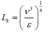
Where:
L.k: Kolmogorov Length Scale
ν: Kinematic Viscosity
EPSε: Energy Dissipation Rate (Use the actual symbols here and anywhere else you define variables Greeks symbols can be found in "Custom Character" while editing in Rich Text mode.)
The two different orifices in the rapid mixer are for the two types of mixing that occur. One is for macro-mixing and the other is for micro-mixing. Macro-mixing mixes the alum to the length scale at which micro-mixing can start. Micro-mixing distributes the eddies to the length scale where molecular diffusion can finish the task.
...
A pipe size/macro-mixing combination can be used for a range of flowrates. An increase in flowrates will result in a higher head loss for the macro-mixing orifice. This can actually result in the macro-mixing orifice having a higher head loss than the micro-mixing orifice. Due to this, the user can select a constraint value for head loss (usually 2 to 10 cm, currently set at 5 cm) that will cap how high the macro-mixing head loss can be. This is done by selecting a larger pipe size and larger macro-mixing orifice. In figure 2, the results for head loss through the macro-mixer are shown below. At high flow-rates, macro-mixing head loss becomes higher than micro-mixing head loss.
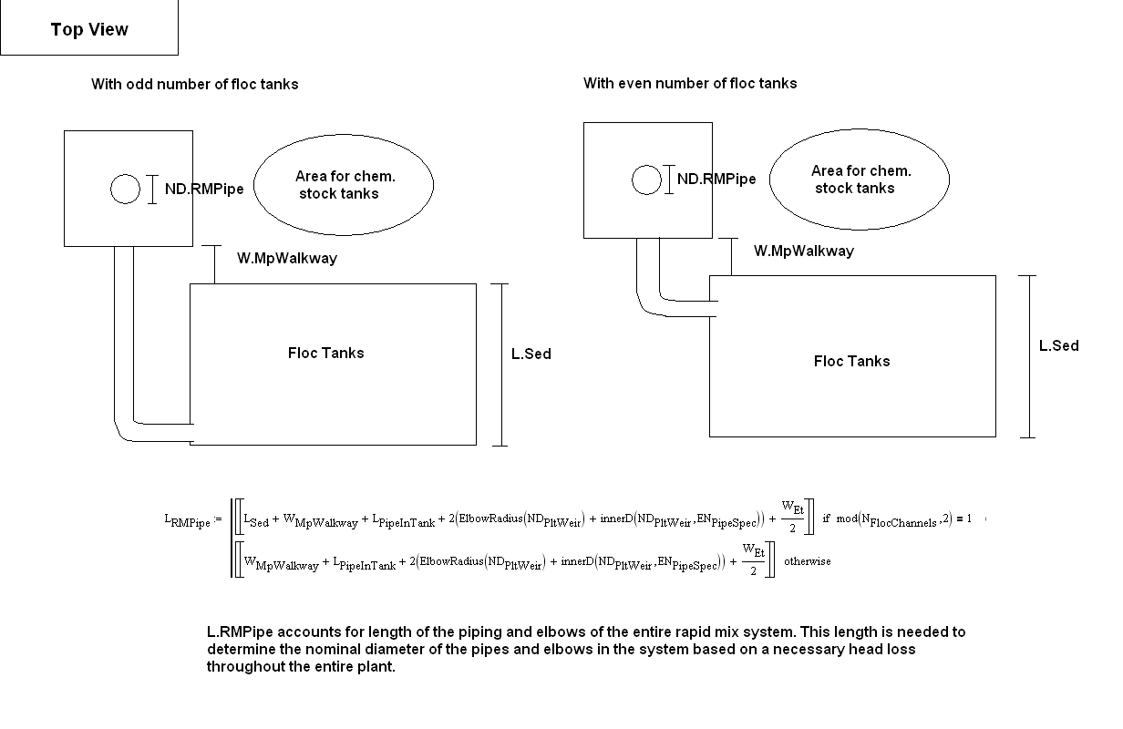
With the head loss of the entire plant and the entire system accounted for the constraint on the macromixer headloss (MacroMHConstraint = 5 cm) the size of the nominal diameter of the pipe, the diameter of the macromix orifice and the size and number of micromix orifices can be determined.
Figure 2: Rapid mix sizing algorithm for lower flow rates with 20 cm through micro-mixer and no constraints
...