 Sign-up for free online course on ANSYS simulations!
| Include Page | ||||
|---|---|---|---|---|
|
Step 4: Setup (Physics)
...
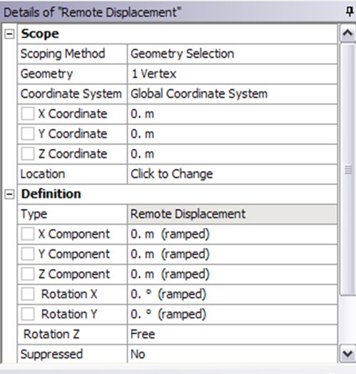
Let's start with setting up boundary condition at A.
Outline > Static Structural (A5) > Insert > Remote Displacement
Select point A in the Graphics window and click Apply next to Geometry under Details of "Remote Displacement". Enter 0 for all UX, UY, UZ, ROTX and ROTY except for ROTZ. Let ROTZ to be free.
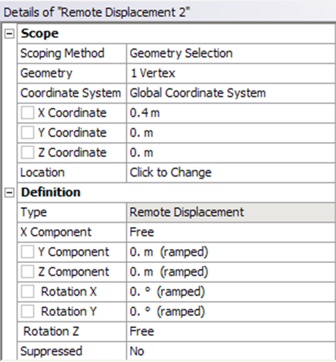
Let's move on to setting up boundary condition B.
Outline > Static Structural (A5) > Insert > Remote Displacement
Select point B in the Graphics window and click Apply next to Geometry under Details of "Displacement 2". Enter 0 for all UY, UZ, ROTX and ROTY except for ROTZ. Let UX and ROTZ to be free.
...
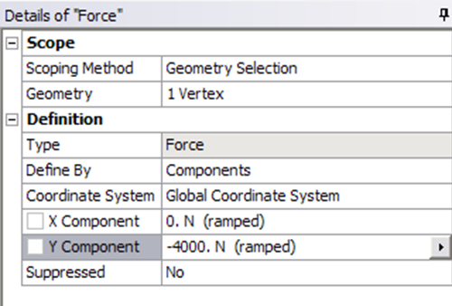
Outline > Static Structural (A5) > Insert > Force
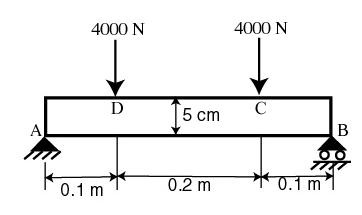
Select point C in the Graphics window and click Apply next to Geometry under Details of "Force". Next to Define By, change Vector to Components. Enter -4000 for Y Component.
Do the same for point D.
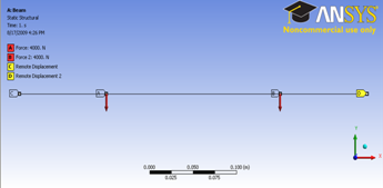
This is what Check that you should have for all the boundary conditions. Click on Static Structural (A5) to view this in Graphics window.
...