 Sign-up for free online course on ANSYS simulations!
...
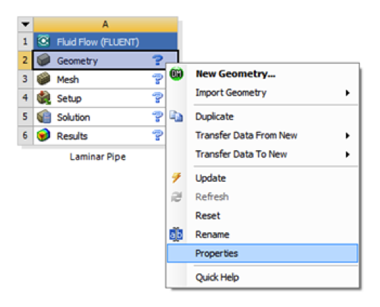
In the Project Schematic of the Workbench window, right click on Geometry and select Properties, as shown below.
The properties menu will then appear to the right of the Workbench window. Under Advance Geometry Options, change the Analysis Type to 2D as shown in the image below.
...
Repeat, and create the second rectangle with smaller length and width. Also, make sure these two rectangles are connected. At this point you should have something comparable to the image below.
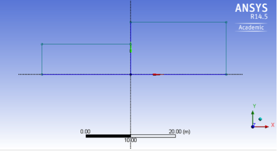
The overlapped lines of these two rectangles are extraneous and will be removed. Under Sketching Toolboxes, click Modify tab, and cut the line indicated by the figure below. This will delete the width of the smaller rectangle.
...
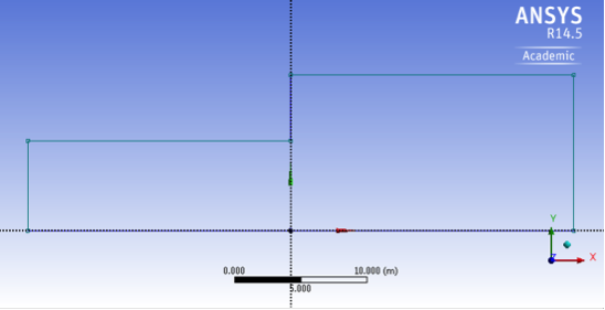
Then, trim the width (only the lower part) of the lager rectangle which overlaps the small rectangle. You should have the image below.
Dimensions
At this point the rectangle will be properly dimensioned.
Under Sketching Toolboxes, select Dimensions tab, use the default dimensioning tools. Dimension the geometry as shown in the following image.
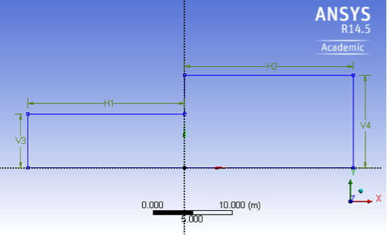
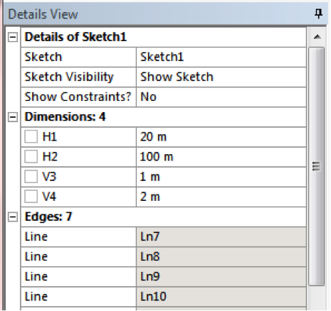
Under the Details View table (located in the lower left corner), set H1=20m, H2=100m, V3=1m and V4 = 2m, as shown in the image below.
Surface Body Creation
In order to create the surface body, first (Click )Concept > Surface From Sketches as shown in the image below.
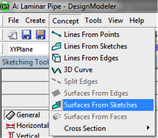
This will create a new surface SurfaceSK1. Under Details View, select Sketch1 (go to XYplane and expand it to see Sketch1, click on it) as Base Objects, and then under Surface body select the thickness to 0.1m and click Apply. Finally right click SurfaceSK1 and select Generate to generate the surface. You should see "1 part, 1 Body" under SurfaceSK1.
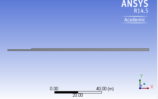
At this point, you can close the Design Modeler and go back to Workbench Project Page. You should see two green check marks next to Geometry and Mesh. Press Refresh Project and Update Project, then save your work thus far in the Workbench Project Page.
...