*** This version of Confluence is for testing only and contains a copy of content from June 29th 2026. No changes will be preserved. ***

...
Our Mathcad design created two designs; one which was a conservative approach (most commonly used), based on the simple hydraulics that the necessary velocity of the backwash is 10 times the velocity of filtration. The second design was based upon empirical equations, called the Weber Equation. The accuracy of the empirical fluidization velocity equations needed to be tested so we developed a bench-scale model of our filtration system and conducted an experiment measuring the expansion of a filter bed as backwash velocity is varied. We then compared the empirically calculated fluidization velocities with the actual fluidization velocities required.
Fluidization Velocity Experiment.
We created the mathcad code to create design parameters for a plant the size of Agalteca with a flow rate of ___________. We compared our two approaches, empirical and conservative (simple hydraulics).
MathCad Results
MathCad Results for a plant flow of 6.3L/day  : Empirical vs. Simple Hydraulics ( Conservative ) Approach
| Conservative | Empirical |
|---|---|---|
Filter Square Side | 1.5m | 1.5m |
Filter Height | 3.95m | 2.56m |
Clear Well Diameter | 6m | 6m |
Clear Well Height | 1.37m | 1.23m |
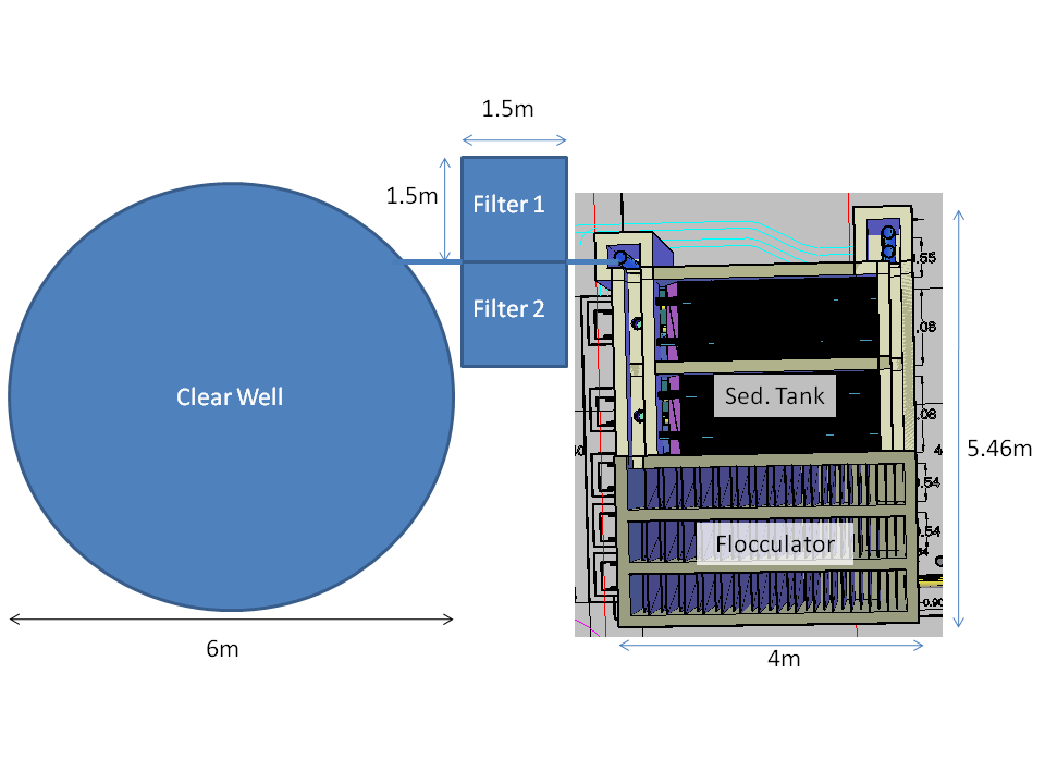
Figure 2: Plan View of Agalteca Plant with Filter Design
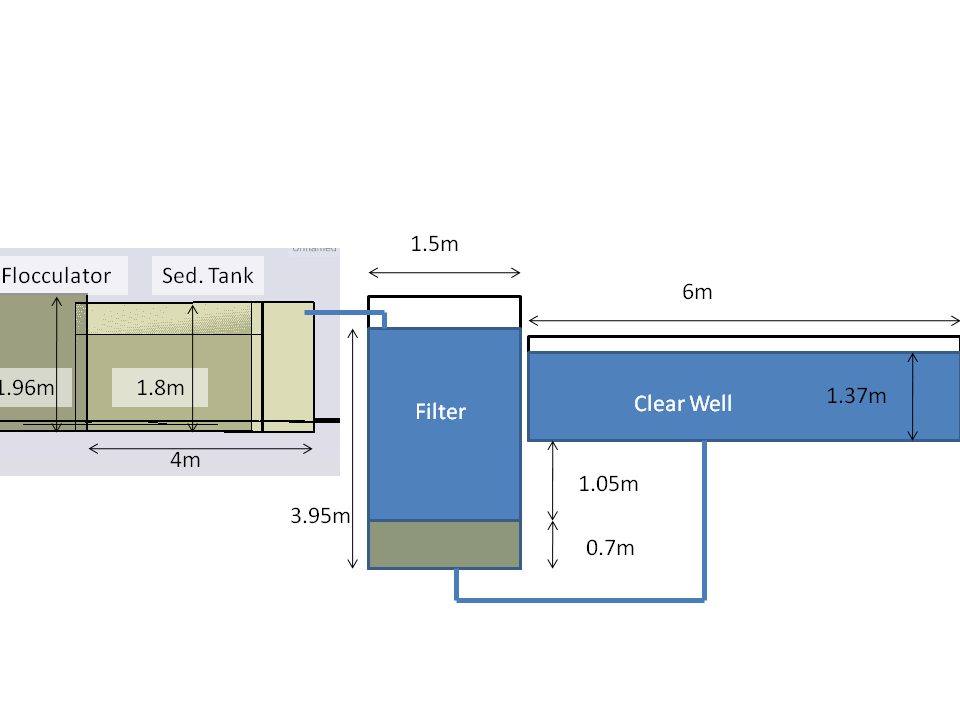
Figure 3: Side View of Agalteca Plant with Filter Design
1) Our design based on simple hydraulics will work. However, it is a very large filter (see exact dimensions in Figure 2) and will not be sustainable economically. The material cost for construction will be too high.
2) The design based on the empirical Weber equation is smaller and less expensive. However, the validity of the empirical equations is not yet certain, in spite of our Fluidization Velocity Experiment. Therefore more testing needs to be done in pilot scale models.
3) If the empirical equations are valid, then we can change parts of the design, by changing the sand parameters. For example, lower the dimensions of the clear well by lowering the backwash velocity by decreasing the d60 and specific weight of the media.
Figure 4: Small Change in D60 can fix the error at 30% Expansion by over 100%
4)An additional advantage to Clear Wells is that the distribution tank does not have to be below the filtration tank, and in fact, it could be the clear well as well.
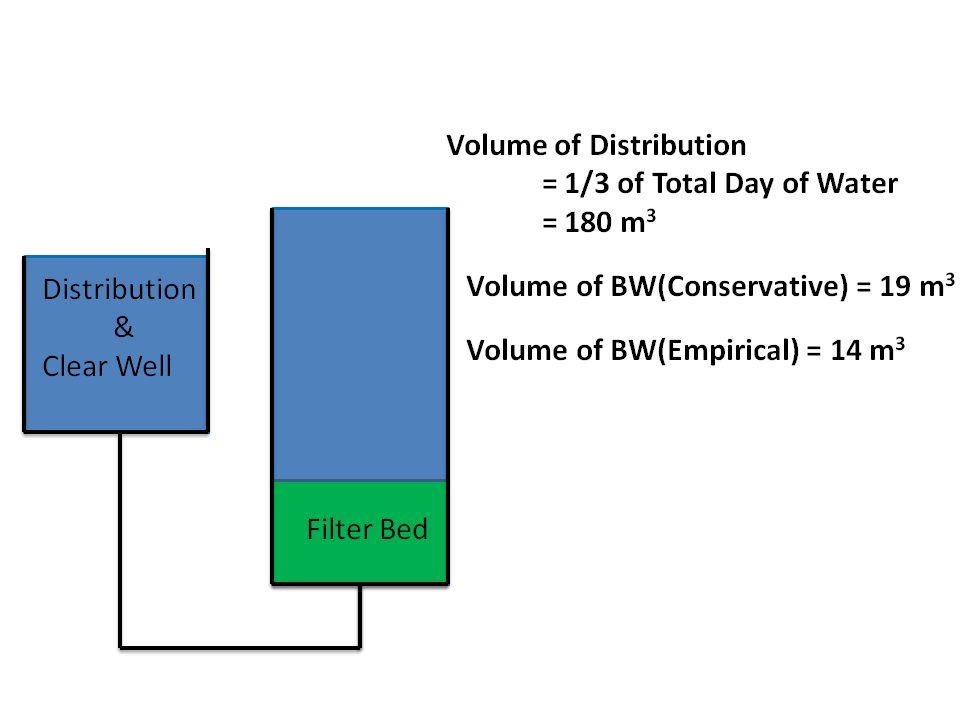
Figure 5: Distribution Tank can be the Clear Well Tank (see Fluidization Velocity Experiment for more specifics)
Experiment Results
We had mixed results with regards to Weber's equation for filter bed expansion. At low levels of filter bed expansion, the Weber equation accurately predicted the fluidization velocity required to achieve the targeted bed expansion. As the target bed expansion increased, so did the degree of error. At 9% expansion, the degree of error was at 14%. At 30% expansion (our target expansion), the degree of error was 110%.
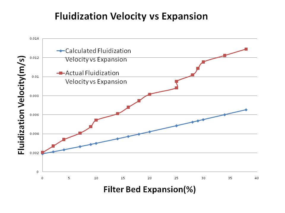
Figure 64: Error Between Calculated and Actual Expansions
...
Despite our best attempt at being consistent (by measuring and marking heights on the test tube, while also holding a ruler on the test tube wall), there will always be human error in observing the bed expansion visually.
Fix: The next expansion experiment should use a camera so there is record of the heights at each flow rate, and also tape a ruler to the filtration bed wall, rather than holding the ruler or drawing it on.Wall Friction:
We can attribute the increase in error as flow rate increased A very small error may be due to the increase in of wall friction on the test vialas the flow rate increased.
Fix: We can minimize the wall and tube friction by increasing the size of our bench scale experiments.
...
We might have used an incorrect D60 and porosity for the filter bed in our equations. We show on the Fluidization Velocity Experiment page how small changes in these values could easily account for the error. T
Fix: For the next experiment those parameters should be tested for the sand or material before conducting experiments.
...
We recommend to do little future research in this area due to the great costs from the large scale of the proposed clear well. Future research into making the sedimentation tank be the backwash source might be fruitful, because this would make the filtration and backwash velocities the same because they are from the same source. However, if there is more research it should be focused on the following:
Future Research should be devoted to the following objectives: