...
- We need to be able to adjust the total head loss through the entire plant to adjust for any extra head loss created in the plant. The easiest way to do this is to change the number of orifices in the Rapid Mix Plate: adding more orifices will reduce the total amount of head loss, and creating a plate with fewer orifices will increase the total head loss through the plant. The following two plots, created in MathCAD, show the variation of head loss with the number of orifices in the micro scale mixing plate for the given maximum Agalteca flow rate of 6.3 L/s and the target energy dissipation rate of 1 W/kg:
! |align=center,width=375,height=335!
...
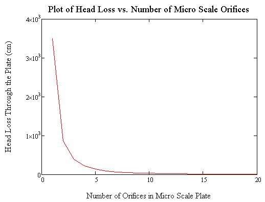 Image Added
Figure 1. Plot of the Head Loss through the micro scale mixing plate against the number of orifices of 7/8" diameter drilled in the plate. As can be seen in the above plot, as the number of orifices in the plate increases, the head loss decreases, showing that increasing the number of orifices in the plate is an effective way of decreasing the head loss through the plate.
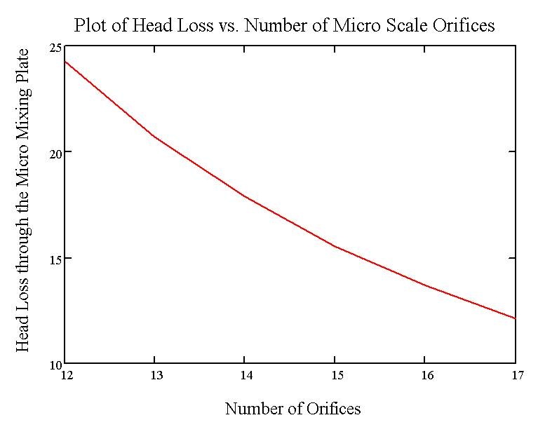 Image Added
Figure 2. Plot of the Head Loss through the micro scale mixing plate against the number of orifices of 7/8" diameter drilled in the plate for a reduced range or number of orifices from 12 to 17, the range of numbers that would be feasible for the micro mixing plate in Agalteca. This plot shows the values of the head loss created through the plate for each number of orifices in the plate, as well as the range of head losses that would be observed in the Agalteca plant for each number of orifices.
The MathCAD file created allows the user to easily input the existing plant parameters such as plant flow and measured head loss, as well as the existing plate characteristics, including the number and diameter of the existing orifices. Using this data, the MathCAD file calculates the total head loss created through the current plate, as well as the target head loss through the plant, and produces the number of extra orifices that must be drilled or taken away from the existing plate to achieve the target head loss through the plant.
...
Another detail that was addressed in the Agalteca Rapid Mix Tube installation was the delivery of the dosed alum into the Rapid Mix Tube itself. To accomplish this delivery, the end of the flexible tubing running off of the doser's level arm was fitted with a small plastic elbow, then attached to the edge of the large scale mixing orifice using a small plastic clip. This allows the alum to be delivered directly into the flow of water entering the tube, improving mixing and reducing the chance that alum will escape into the entrance tank.
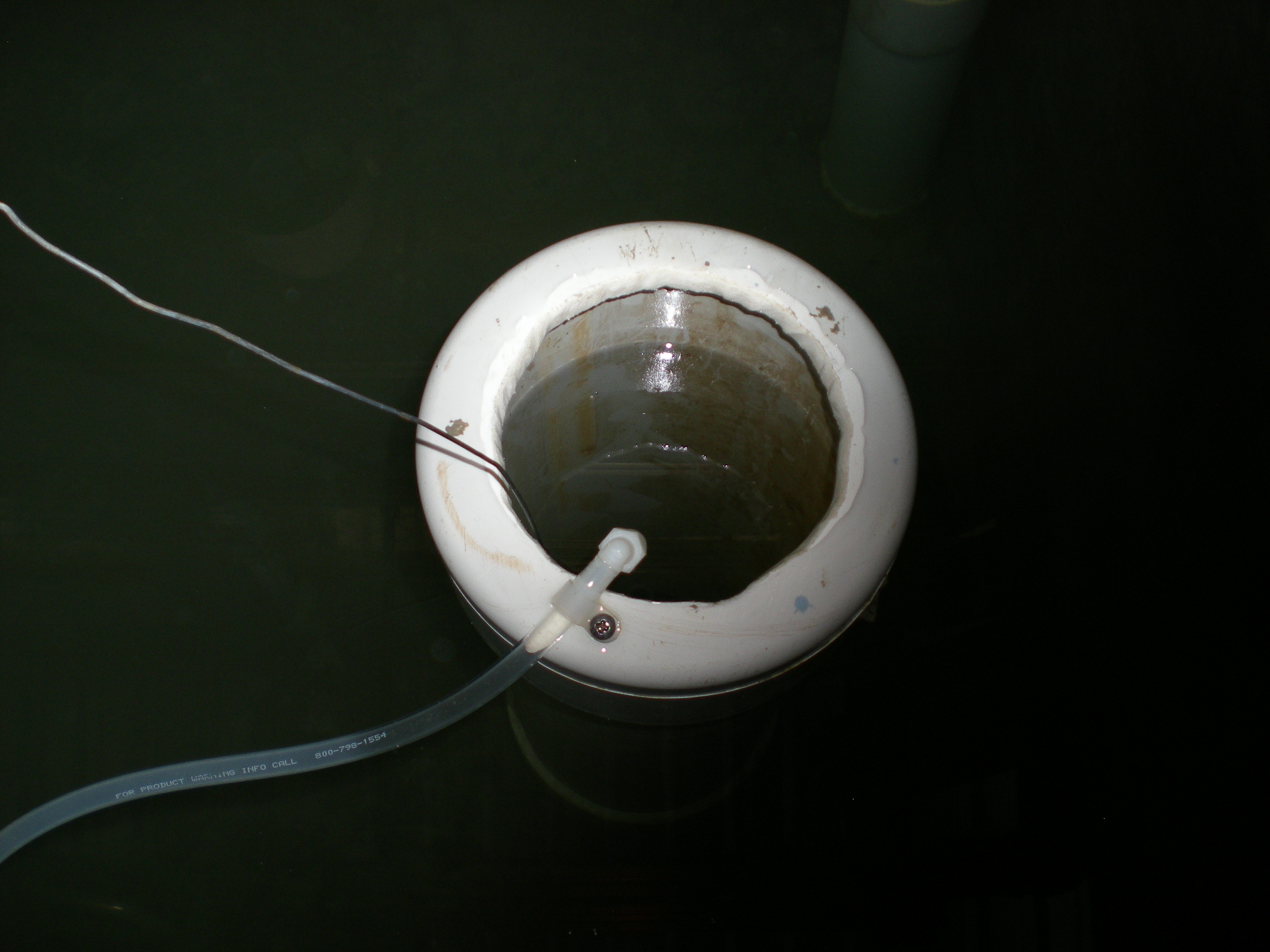
Figure
...
3. Photo of the attachment of the aluminum sulfate dosing tube to the top of the Rapid Mix Tube in the Agalteca plant. The wire in the left of this photo is attached to the Rapid Mix Plate; this allows for easier removal of the plate as the operator can simply pull it out of the tube instead of reaching into the tank to retrieve the plate.
Deliverables
- Modified MathCAD file to achieve target head loss using rapid mix plate adjustments
- This MathCAD file is used to adjust the rapid mix plate orifice number and sizing to create the target head loss through the plant. It can also estimate the head loss through the flocculator, a variable of interest, as well as adjust the allowable orifice sizes for the rapid mix plate based on the actual maximum flow rates for the plant, which likely differ from those estimated for the design.
