...
Preliminary experiments have indicated the need for an accumulation chamber to feed the rapid mix tube display in place of a direct siphon line from the dosing tank. A direct siphon line creates a lot of mixing in the upper portion of the tube, negating the visual effects of the display. Thus, to create a 'calmer' flow into the rapid mix tube, we will introduce a chamber, directly fed by the siphon that will provide a steady flow into the rapid mix tube and allow for better visualization of the chemical mixing processes. Photos of the dye flow through the system will be posted as soon as they are taken after further experimentation
More dye experiments were performed through the remainder of the Spring 2010 semester leading up to the EPA conference. The following images were captured during on of these experiments. It should be noted that the flow of water and dye through the rapid mix display tube were altered to provide a good visual, conceptual effect for these demonstrations. When operating as designed in AguaClara plants, the alum (represented by the dye) will immediately appear dispersed throughout the upper portion of the tube following the macro-scale mixing orifice; this scale tube produces this uniform mixing immediately when run using the same parameters it would encounter in plant flow, however, only photos of the display parameters are shown here:
| Multimedia |
|---|
| name | dye addition video.avi |
|---|
| width | 400 |
|---|
| height | 335 |
|---|
|
Figure 3. This video of the dye addition to the tube was performed in the AguaClara laboratory in Spring 2010 after the scale model of the tube was completed. It shows the addition and flow of dye through the tube over a period of time, allowing viewers to see the process and overall mixing occurring in both the macro and micro scale mixing portions of the tube.
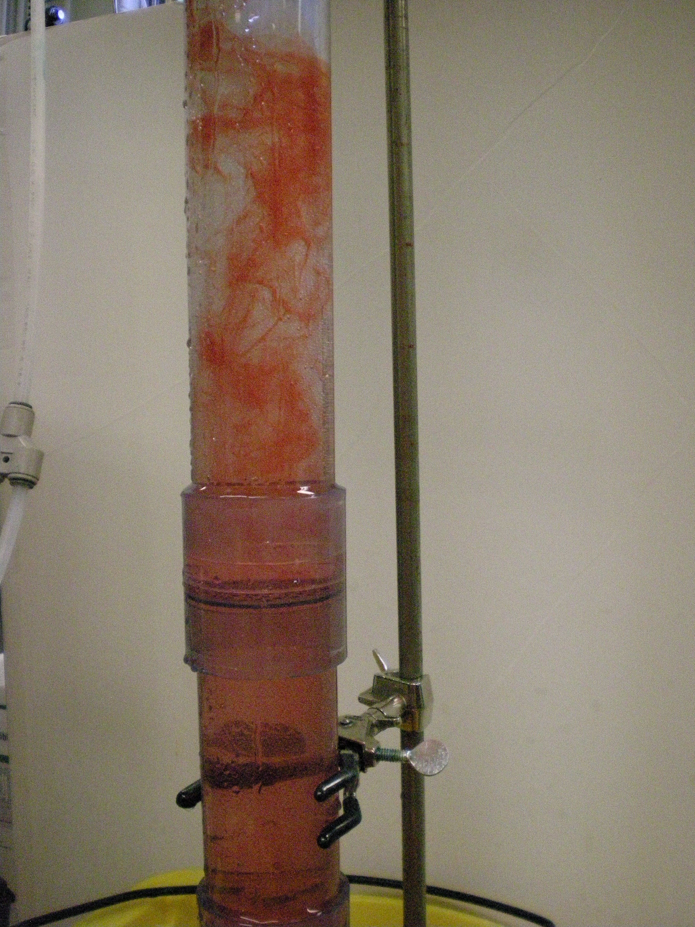 Image Added
Figure 4. This photo shows the full length of the tube during a dye addition; one can see the large-scale eddies produced in the upper, macro scale mixing portion of the tube, as well as the nearly uniform mix being produced in the micro scale mixing portion of the tube following the micro scale mixing orifice.
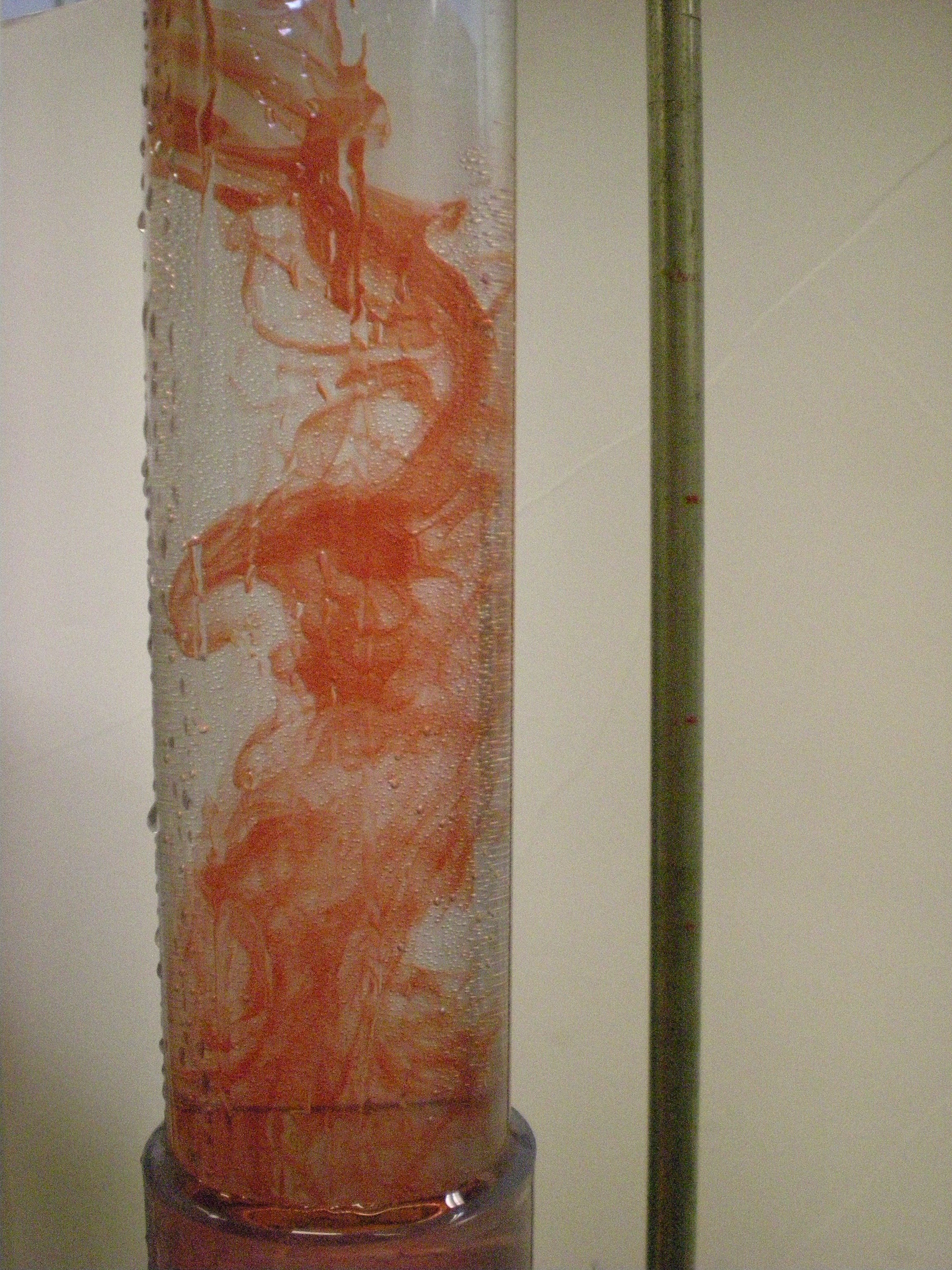 Image Added
Figure 5. This photo provides a close-up shot of the large scale eddies being produced in the macro scale mixing portion of the tube following entry of the water through the macro scale mixing orifice and addition of the dye just below the point of that orifice .
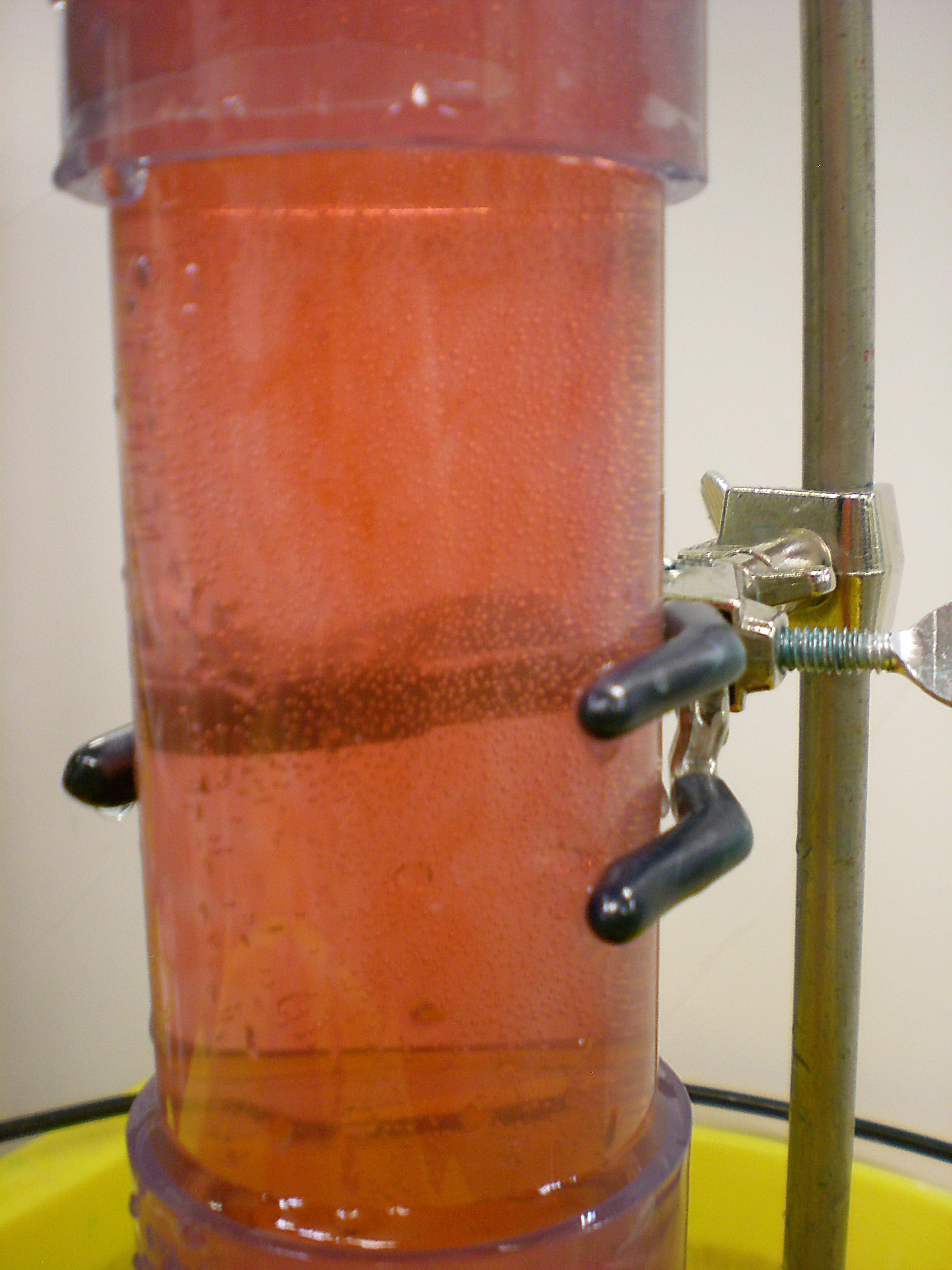 Image Added
Figure 6. This photo provides a close-up shot of the lower, micro scale mixing portion of the tube as the macro-mixed water and dye mixture travel through the micro scale mixing orifice. As can be seen by the near uniformity of the water-dye mixture in this portion of the tube, the water and dye are mixing down to the micro scale level after the micro scale mixing orifice, creating greater contact and mixing between water and dye particles.
Deliverables
- EPA scaled Rapid Mix Tube Design
- This MathCAD file calculates all of the parameters of the flow needed, as well as the sizes of the small and large scale mixing orifices required to achieve a good visual display in the clear PVC rapid mix tube demonstration.
