*** This version of Confluence is for testing only and contains a copy of content from June 29th 2026. No changes will be preserved. ***

...
In the case of macro-mixing, we are setting the minor loss coefficient to 1.3. This value is assumed to be adequate to allow for macro-mixing. The total head loss through the rapid mixer is set to 20 - 50 cm accounts for a total head loss of 40 cm throughout the entire plant, with most of the head loss in the rapid mix system belonging to the micro-mixer. This will be needed for the dose controller that will be integrated into the system. The dose controller uses a flow measurement device which relates head loss to flowrate (See Lectures on Rapid Mix). From the equation for a submerged orifice, it can be seen with the design assumption of K = 1.3, each pipe size will allow for one macro-mixing orifice size.
A A pipe size/macro-mixing combination can be used for a range of flow-rates. An increase in flow-rates will result in a higher head loss for the macro-mixing orifice. This can actually result in the macro-mixing orifice having a higher head loss than the micro-mixing orifice. Due to this, the user can select a constraint value for head loss (usually 2 to 10 cm, currently set at 5 cm) that will cap how high the macro-mixing head loss can be. This is done by selecting a larger pipe size and larger macro-mixing orifice. In figure 2, the results for head loss through the macro-mixer are shown below. At high flow-rates, macro-mixing head loss becomes higher than micro-mixing head loss.
Figure 2: Rapid mix sizing algorithm for lower flow rates with 20 cm through micro-mixer and no constraints
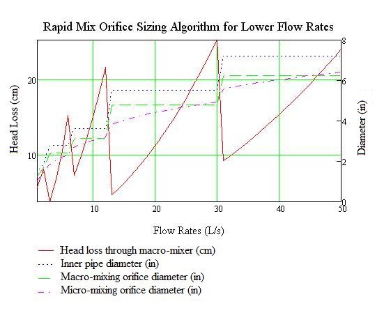
The The results show that above that with each pipe size and macro-mixing size, we have high head losses through the macro-mixing orifice which will increase to levels greater than 20 cm and hence give most of the head loss through the micro-mixing orifice.
The algorithm can be summarized in these following steps:
1. Determine the inner pipe size given the flow-rates, maximum pressure drop (20 to 50 cm). total minor loss coefficients, and the available pipe sizes. The user also sets a constraint or limit for the macro-mixing orifice head loss.
...
4. Use the assigned total head loss value (20-50 cmcalculated to provide 40 cm of loss in the entire system) and maximum flow rate to determine the minor loss coefficient needed for the micro-mixing orifice. Using the equation for minor loss coefficients for submerged orifices to determine the orifice diameter for the micro-mixing orifice. The number of orifices that can fit the area of the micro-mixing interface is returned based on the micro-mixing diameter.
Running this algorithm for flow-rates under 50 L/s gave the following results as shown below on Figure 3.
Figure 3: Rapid mix sizing algorithm for lower flow rates with 50 cm maximum head loss and 2 cm constraint on macro-mixer
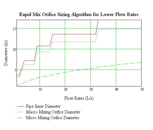
We also did runs where the constraint was raised to 10 cm head loss through the macomacro-mixing orifice.
Figure 4: Rapid mix sizing algorithm for lower flow rates with 50 cm maximum head loss and 10 cm constraint on macro-mixer
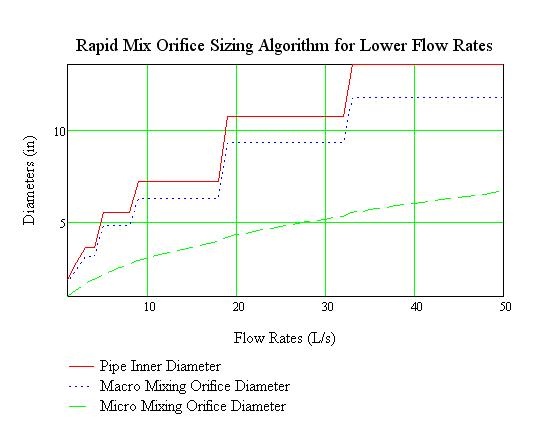
With this lower constraint, we find much smaller pipe sizes used. The micro-mixing orifices are also larger. We can also change the results to see what happens when we want a 20 cm head loss through the rapid mixer with our 2 cm constraint through the macro-mixer.
...