*** This version of Confluence is for testing only and contains a copy of content from June 29th 2026. No changes will be preserved. ***

...
The rapid mix system is designed to accomplish this. The rapid mix design consists of piping leading from the entrance tank to the flocculator entrance. The piping contains two orifices. The orifices decrease the cross sectional area of the flow allowing for a higher velocity and thus turbulence. Turbulence, measured in energy dissipation rate, is associated with the formation of eddies which mix the alum to the length scale at which viscosity overrides the formation of eddies with a larger energy dissipation rate being associated with a smaller eddies. The length scale at which the eddies can mix the alum to is known as the Kolmogorov length scale.

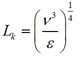
Where:
L.k: Kolmogorov Length Scale
...
In the current design, we have two circular orifices on the same pipe segment. Originally, the micro-mixing orifice was after the first pipe bend. However we have decided to change that to allow facility of removal when cleaning is required. The micro-mixing orifice is two pipe diameters below the macro-mixing orifice. This ensures adequate mixing time for macro-mixing to take effect. The orifices for both equations are sized using the equations of minor loss coefficient for a submerged orifice. 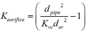
Where:
K.e.orifice: Minor loss Coefficient
K.vc: Vena Contracta Coefficient
d.pipe: Pipe Inner Diameter
d.orifice: Orifice Diameter
The equation for head loss is shown below:
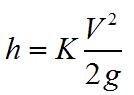
Where:
h: Head Loss
K: Minor Loss Coefficient
V: Velocity of Fluid
G: Gravitational Constant
...
A pipe size/macro-mixing combination can be used for a range of flow-rates. An increase in flow-rates will result in a higher head loss for the macro-mixing orifice. This can actually result in the macro-mixing orifice having a higher head loss than the micro-mixing orifice. Due to this, the user can select a constraint value for head loss(usually 2 to 10 cm) that will cap how high the macro-mixing head loss can be. This is done by selecting a larger pipe size and larger macro-mixing orifice. In figure 2, the results for head loss through the macro-mixer are shown below. At high flow-rates, macro-mixing head loss becomes higher than micro-mixing head loss.
Figure 2: Rapid mix sizing algorithm for lower flow rates with 20 cm through micro-mixer and no constraints 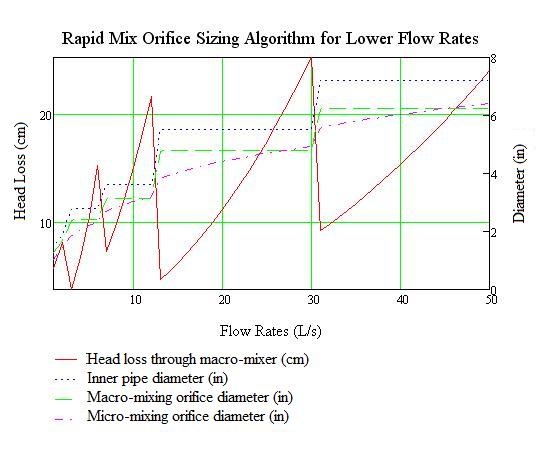
The results show that above that with each pipe size and macro-mixing size, we have high head losses through the macro-mixing orifice which will increase to levels greater than 20 cm and hence give most of the head loss through the micro-mixing orifice.
The algorithm can be summarized in these following steps:
1. Determine the inner pipe size given the flow-rates, maximum pressure drop (20 to 50 cm). total minor loss coefficients, and the available pipe sizes. The user also sets a constraint or limit for the macro-mixing orifice head loss.
...
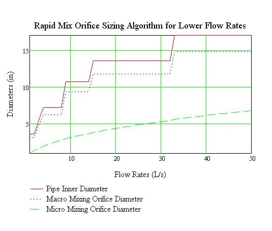
Running this algorithm for flow-rates under 50 L/s gave the following results as shown below on Figure 3.
Figure 3: Rapid mix sizing algorithm for lower flow rates with 50 cm maximum head loss and 2 cm constraint on macro-mixer
We also did runs where the constraint was raised to 10 cm head loss through the maco-mixing orifice.
Figure 4: Rapid mix sizing algorithm for lower flow rates with 50 cm maximum head loss and 10 cm constraint on macro-mixer
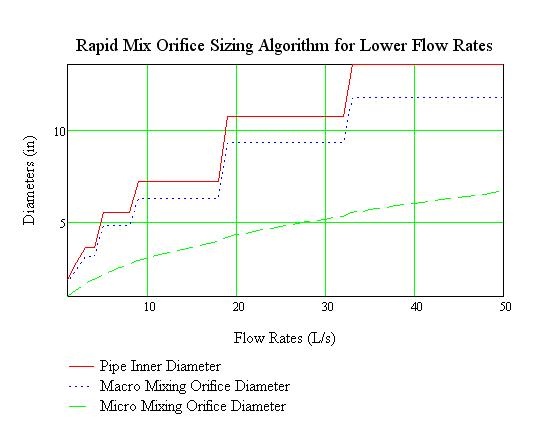
With this lower constraint, we find much smaller pipe sizes used. The micro-mixing orifices are also larger. We can also change the results to see what happens when we want a 20 cm head loss through the rapid mixer with our 2 cm constraint through the macro-mixer.
Figure 5: Rapid mix sizing algorithm for lower flow rates with 20 cm maximum head loss and 2 cm constraint on macro-mixer
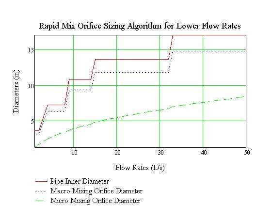
The results for the pipe sizing and and macro-mixer sizing are not changed but we have larger orifices.
The next task is to use this code in developing an AutoCAD image of the entrance tank and rapid mixer.