*** This version of Confluence is for testing only and contains a copy of content from June 29th 2026. No changes will be preserved. ***

...
In the case of macro-mixing, we are setting the minor loss coefficient to 1.3. This value is assumed to be adequate to allow for macro-mixing. The total head loss through the rapid mixer is set to 20 - 50 cm with most of the head loss belonging to the micro-mixer. This will be needed for the dose controller that will be integrated into the system. The dose controller uses a flow measurement device which relates head loss to flowrate (See Lectures on Rapid Mix). From the equation for a submerged orifice, it can be seen with the design assumption of K = 1.3, each pipe size will allow for one macro-mixing orifice size.
...
Figure 5: Rapid mix sizing algorithm for lower flow rates with 20 cm maximum head loss and 2 cm constraint on macro-mixer
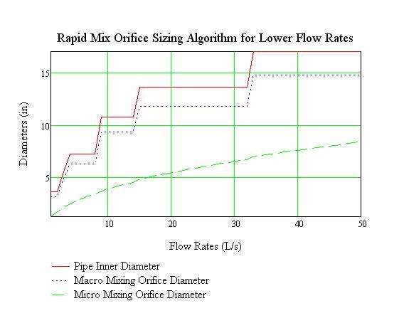
The results for the pipe sizing and and macro-mixer sizing are not changed but we have larger orifices.
The current work is now coding this onto the AutoCAD along with entrance tank. The next task is to use this code in developing an AutoCAD image of the entrance tank and rapid mixer.