*** This version of Confluence is for testing only and contains a copy of content from June 29th 2026. No changes will be preserved. ***

...
The equation for minor loss coefficients for a submerged orifice shown above is used to find the orifice diameter needed.
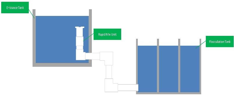
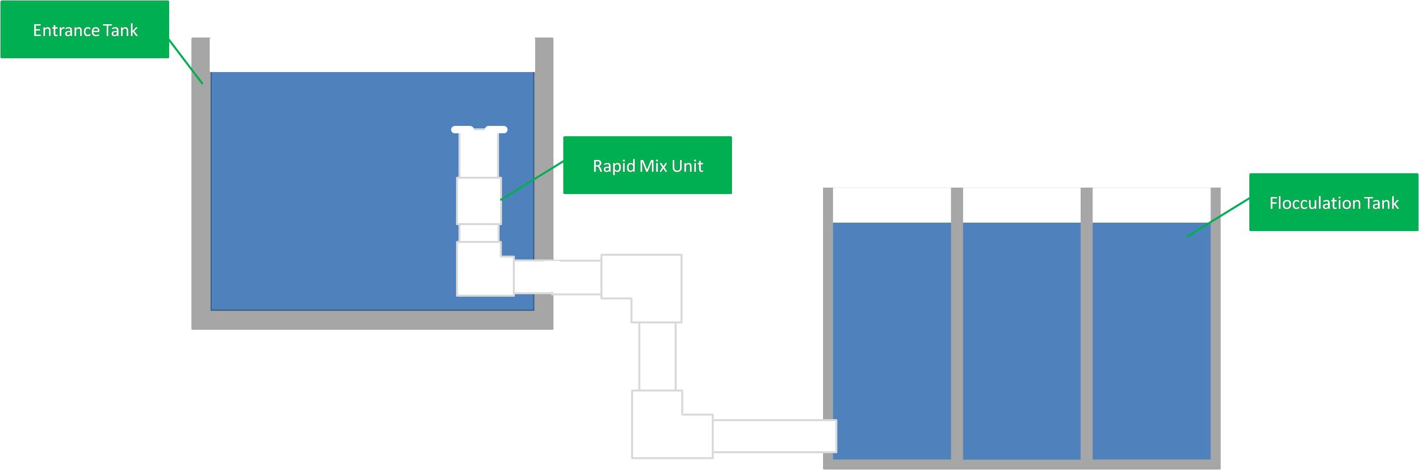 Figure 1: Design Layout of Rapid Mix System
...
A pipe size/macro-mixing combination can be used for a range of flow-rates. An increase in flow-rates will give that result in a higher head loss for the macro-mixing orifice a significant head loss. This can actually result in the macro-mixing orifice having a higher head loss than the micro-mixing orifice. Due to this, the user can select a constraint value for head loss(usually 2 to 10 cm) that will cap how high the macro-mixing head loss can be. This is done by selecting a larger pipe size and larger macro-mixing orifice. In figure 2, the results for head loss through the macro-mixer are shown below. At high flow-rates, macro-mixing head loss becomes higher than micro-mixing head loss.
...