*** This version of Confluence is for testing only and contains a copy of content from June 29th 2026. No changes will be preserved. ***

...
The AguaClara team is revising a design for smaller flow rates (under 50 L/s). This page will document and describe the current changes in the Rapid Mix system and the algorithm for preparing an AutoCADD drawing of the Rapid Mix system. The rapid mixer system sizing algorithm is presented is here. Currently, we are now developing an algorithm to plot the entrance tank and rapid mixer onto an AutoCAD drawing.
The suspended particles in the water are removed through a process known as sedimentation. The rate of sedimentation is increased by increasing the diameter of the particles through sticking them together. This is done in a process known as flocculation. Alum is the coagulant of choice used to cause the particles to undergo flocculation. This has to be done rapidly as to ensure the aluminum sulfate does not precipitate before it can be used by the particles. We also need even distribution of alum to the molecular level.
...
In the current design, we have two circular orifices on the same pipe segment. Originally, the micro-mixing orifice was after the first pipe bend. However we have decided to change that to allow facility of removal when cleaning is required. The micro-mixing orifice is two pipe diameters below the macro-mixing orifice. This ensures adequate mixing time for macro-mixing to take effect. The orifices for both equations are sized using the equations of minor loss coefficient for a submerged orifice.
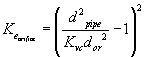
Where:
K.e.orifice: Minor loss Coefficient
K.vc: Vena Contracta Coefficient
d.pipe: Pipe Inner Diameter
d.orifice: Orifice Diameter
...
Research has estimated that for a macro-mixing orifice, we should have a minor loss coefficient of 1.3. This is what we are using for our design. In the case of a macro-mixing orifice, each pipe diameter allows for one orifice size. An increase in flow-rates will give the macro-mixing orifice a significant head loss. In the algorithm, if there is significant head loss above a certain limitation (2 cm or above), then the piping is upgraded to the next size. The reason for having a minimum flow-rate for macro-mixing is that we plan There were plans to use the macromicro-mixing orifice as a losses for flow -measurement device which can handle 20-50 cm maximum head loss at maximum flow-rate. The micro-mixing orifice is sized for a minor loss coefficient that allows for this type of flow and head lossmeasurement and due to this it was thought that there should be a constraint on the head loss through the micro mixer. To accomplish this, the pipe sizing algorithm is modified to select pipe sizes that will meet this constraint.
The equation for head loss is shown below:

Where:
h: Head Loss
K: Minor Loss Coefficient
V: Velocity of Fluid
G: Gravitational Constant
...
4. Use the assigned total head loss value (20-50 cm) and maximum flow rate to determine the minor loss coefficient needed for the micro-mixing orifice. Using the equation for minor loss coefficients for submerged orifices to determine the orifice diameter for the micro-mixing orifice.For a flow rate of 1 L/s with 50 cm maximum head loss, we obtained an inner pipe diameter of 1.89 in and macro-mixing and micro-mixing orifice diameters of 1.64 in and 0.94 in respectively. For the case of 2 L/s with 50-cm maximum head loss, we obtained an inner pipe diameter of 2.80 in and macro-mixing and micro-mixing diameters of 2.42 in and 1.33 in respectively. There will be changes made to make this algorithm more robust and they are in process. In the cases of higher flow-rates, it is better to transition to the waterfall rapid mix design that the research team came up with before.
Running this algorithm for flow-rates under 50 L/s gave the following results as shown below on Figure 2.
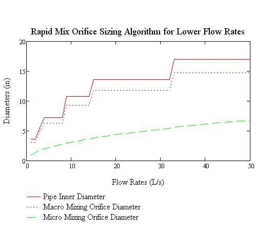
Figure 2: Rapid Mix Orifice Sizing Algorithm for Lower Flow Rates