*** This version of Confluence is for testing only and contains a copy of content from June 29th 2026. No changes will be preserved. ***

...
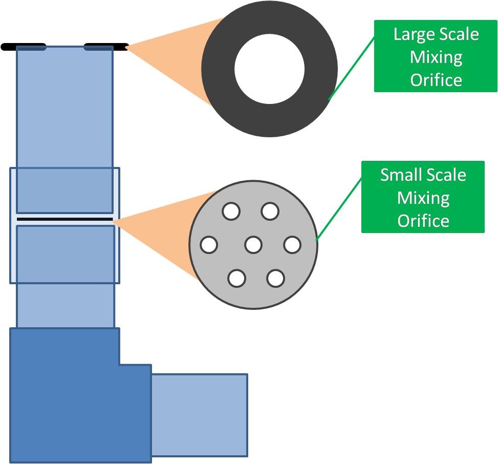
The current design for the rapid mix tube was developed to address the problems created by the initial design. A schematic of the new design is shown in Figure 32. This new rapid mix tube system consists of two separate 'stages,' a large-scale mixing process in the first portion of the system, and small-scale mixing process in the second portion. The tube protrudes up into the entrance tank to help regulate flow through the plant-flow through the plant will cease once the water level in the entrance tank reaches the top of the rapid mix tube, allowing the water already in the tank to be stored if there is low source flow or the plant needs to be cleaned.
...
Large-Scale Mixing Orifice Design
...
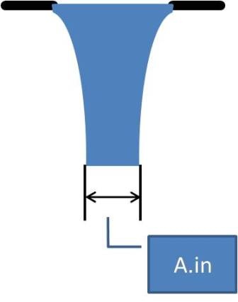
In this equation, A.in is taken to be the area of contracted flow through the orifice, which is the area of the large-scale mixing orifice multiplied by the vena contracta coefficient, which accounts for the contraction of flow through an orifice. The equation the describes this is as follows:
Figure 4 3 illustrates the effect of the water contraction flowing through an orifice.
...
A.out in the above equations is taken to be the area of the pipes used in the system since the water is allowed to outlet freely into these pipes.
...
The area of the small scale orifice can be either cirucular or rectangular in shape, again depending upon the plant flow rate, desired energy dissipation rate, and desired head loss through the small-scale orifice. A diagram of some possbile orifice configurations is shown below in Figure 4.
Insert Figure 4 here--the different orifice designs
5. Each of these designs is preferred in different cases depending on the plant flow rate, pipe diameter, desired head loss, and desired energy dissipation rate. Tentatively, the Agalteca plant will feature a small-scale orifice featuring the multiple round orifices, which will best serve this plant in evenly mixing the aluminum sulfate dosed to the raw waste, as well as achieving the desired energy dissipation rate through the orifice. To calculate the dimensions of the round orifices that will occur in the small-scale mixing orifice, the following equation in used:
...
Here, ε is the value of the maximum energy dissipation rate for the plant, and the orifice is thus designed to achieve this value. Δh is the same target value for the head loss from the small-scale orifice design equation. This equation thus calculates the maximum minimum dimension of a rectangular orifice. This dimension can be adapted to the proposed Agalteca design with multiple small orifices, however, because of the presence of many small orifices in entire small-scale mixing orifice. The dimension calculated in this equation will then be used as the diameter of the multiple orifices that must be put into the small-scale mixing orifice. Figure 6 5 provides a schematic of the rapid mix tube as well as the placement of the two orifices and a detail of the multiple-orifice small scale mixing orifice that will likely be used in the Agalteca plant.
...
Headloss Calculations and Significance
The total headloss through the system is comprised of minor losses, caused by water flow through the orifices and through pipe fittings such as elbows, and major losses due to friction on the pipe walls. The equation used to calculate total headloss through the system is:
...
Here, HL.LargeScaleMixing and HL.SmallScaleMixing refer to the minor losses through the large and small scale mixing orifices, respectively. HL.PipeFittings and HL.PipeFriction are caused by minor losses through the pipe fittings and major losses sue to shear along the pipe walls.
...
Need a ~paragraph here explaining how the head losses for each component are calculated
The calculation of the headloss through the system is important because the headloss through the rapid mix tube system partially determines the change in height of the water in the entrance tank when the plant flow changes. The nonlinear chemical doser is designed to change the flow rate of alum with the flow rate of the plant, and it is thus very important to calculate the headlosses through the rapid mix tube system and the sections of the plant following it in order to correctly design the chemical doser to maintain a constant concentration of alum in the raw water source despite changing flow rates.
Work throughout the rest of the fall 2009 semester will focus on finalizing the Agalteca plant rapid mix tube design. The rapid mix subteam will also build a full-scale model of the system in order to test the feasibility of the system as well as create a prototype tube on which to base future improvements to the tube. Experiments will also be carried out to test the flow of water through the system as well as the effectiveness of the orifices in creating rapid mix of chemical introduced to the water source flowing through the tube system.
...