*** This version of Confluence is for testing only and contains a copy of content from June 29th 2026. No changes will be preserved. ***

...
Water enters the top of the tube through the large-scale mixing orifice, where it is dosed with the aluminum sulfate and begins the rapid mix process. This orifice is in place to create large scale mixing in the first section of the tube. The design of this orifice size is based on the exit loss coefficient through the orifice, K. The target K value for this orifice is 2, which provides the best mixing in the first section of the tube for large-scale rapid mix. To calculate the necessary area and diameter of the large scale mixing orifice, the following equation was used:
Solving for A.in, which will be the area of the stream of water entering the tube through the orifice, we obtain:
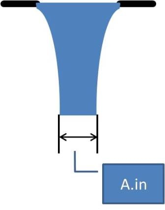
In this equation, A.in is taken to be the area of contracted flow through the orifice, which is the area of the large-scale mixing orifice multiplied by the vena contracta coefficient, which accounts for the contraction of flow through an orifice, which is shown in Figure 4. The equation the describes this is as follows:
Figure 4 illustrates the effect of the water contraction flowing through an orifice.
A.out in the above equations is taken to be the area of the pipes used in the system since the water is allowed to outlet freely into these pipes.
List references for your project that your team has found in literature searches.
What do you plan on "handing in" by the end of the semester? Designs, programs, separate reports for publication, etc.