*** This version of Confluence is for testing only and contains a copy of content from June 29th 2026. No changes will be preserved. ***

...
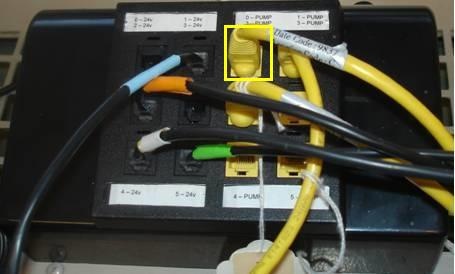
The next step is to connect the pump to interface with the computer. You can do this through a teethed cable that will connect and plug in the RJ45 cable (looks like an ethernet cable) to the persistaltic pump control portion on the stamp box (yellow).
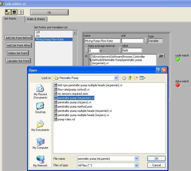
After you have made the pump connection, you want to program into the computer the flow rate of the pump. We can do this through what is known as VI code. Create a new setpoint and name the setpoint "Mixing Pump Flow Rate." Click on the setpoint and reset the type of setpoint from constant to variable.
Constant means that throughout the experimental run, the same value will be used by the computer to make calculations to run valves and pumps. Variables means that the computer will run a calculation before sending the signal to the stamp box.
Click on the folder icon to open the VI: peristaltic pump (mLpermin).vi under the file directory: \\Enviro\enviro\Software\Process Controller methods\Peristaltic Pump\peristaltic pump (mLpermin).vi . These steps are highlighted in the figure below.
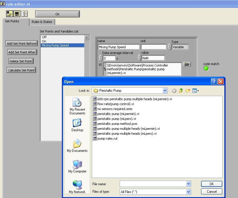
The purpose of this VI is to calculate the rpm speed of the pump. The rpm will set the flow rate supplied to the system based upon the tubing size. The computer will calculate the speed of the pump, but requires that you make two additional set points. Note: Put your set points in order of how they are calculated
Create two new set points:
Figure 4 Clay Flow Rate Setup
...