 Sign-up for free online course on ANSYS simulations!
...
Dimensions and Constraints
We start by constraining the top edges and bottom edges. We want to top edge to correspond to the lower edge. Under Sketching Toolboxes, select Constraints tab. The constraint box will appear. Select Dimensions tab, use the default dimensioning tools. Dimension the geometry as shown: 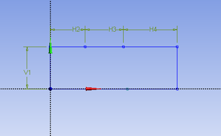
Now we need to constraint the lower rectangle with the top of the rectangle which has been properly dimensioned. Click Constraints tab, select Equal Length. Click the appropriate top and bottom edge and set them to be of equal length.
Now that top and lower edges are properly constrained, we can dimension our geometry. Under Sketching Toolboxes, select Dimensions tab, use the default dimensioning tools. Dimension the geometry as shown:
Under Details View on the lower left corner, input the value for dimension appropriately.
V1: 0.05 m
H2: 0.1 m
H3: 0.2 m
H4: 0.1 m
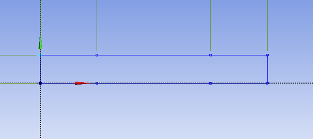
At this point, you should see something like this for your sketch:
Create Surface
Now that we have the sketch done, we can create a surface for this sketch.
Concept > Surfaces From Sketches
This will create a new surface SurfaceSK1. Under Details View, select Sketch1 as Base Objects and click Apply. Finally click Generate  to generate the surface. This is what you should see under your Tree Outline.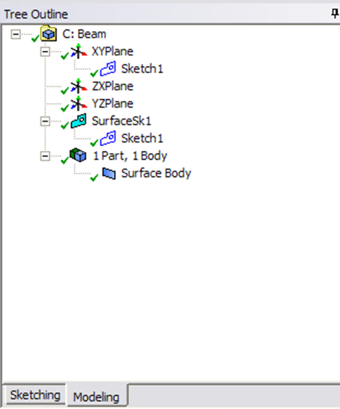
You can close the Design Modeler and go back to Workbench (Don't worry, it will auto save).
See and rate the complete Learning Module
...