 Sign-up for free online course on ANSYS simulations!
| Include Page | ||||
|---|---|---|---|---|
|
Step 2: Geometry
Our geometry is 2D. At Workbench, in the Beam cell, right click on Geometry, and select Properties. You will see the properties menu on the right of the Workbench window. Under Advance Geometry Options, change the Analysis Type to 2D. 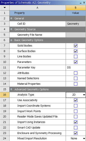
In the Project Schematic, double left click on Geometry to start preparing the geometry.
At this point, a click New Geometry... A new window, ANSYS Design Modeler will be opened. You will be asked to select desired length unit. Select Meter Use the default meterunit and click OK.
Strategy for Geometry Creation
We need to apply point boundary conditions at four points A, B, C and D shown in the figure below. In ANSYS, point boundary conditions are applied to nodes. When we mesh the rectangle using the ANSYS Mesher, nodes will automatically be created at A and B since these are corner points; the corresponding displacement BC's can be applied to these corner nodes. However, there is no guarantee that there will be nodes exactly at C and D since these are not corners. In this case, ANSYS will apply the forces at the nodes that are closest to C and D. This is possibly acceptable if the mesh is sufficiently fine. 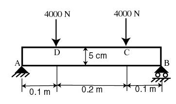
An alternative scenario is that we get clever and force C and D to be exact points. This can be done by splitting the top and bottom edges into three section as shown below. This will force nodes to be created at points C and D. Then, the point forces can be applied to these nodes. This is the strategy we'll use in creating the geometry. 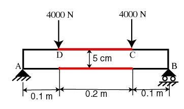
Creating a Sketch
Like any other common CAD modeling practice, we start by creating a sketch.
...